PARK / NEUTRAL POSITION SWITCH INSTALLATION

-
INSTALL PARK/NEUTRAL POSITION SWITCH ASSEMBLY
Tech Tips
Make sure that the manual valve lever shaft has not been rotated prior to installing the park/neutral position switch assembly as the detent spring may become detached from the manual valve lever shaft.
-
Install the park/neutral position switch assembly to the manual valve lever shaft.
-
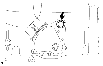
Temporarily install the bolt.
-
Install a new lock washer with the nut.
- Torque:
- 6.9 N*m { 70 kgf*cm, 61 in.*lbf }
-
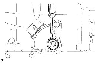
Temporarily install the control shaft lever with shifting rod.
-
Turn the control shaft lever counterclockwise until it stops, and then turn it clockwise 2 notches to set it to N.
-
Remove the control shaft lever with shifting rod.
-
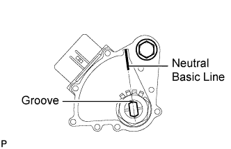
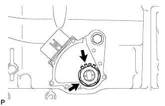
Align the groove with the neutral basic line.
-
Hold the park/neutral position switch assembly in this position and tighten the bolt.
- Torque:
- 13 N*m { 130 kgf*cm, 9 ft.*lbf }
-
Using a screwdriver, bend the tabs of the lock washer.
Tech Tips
Bend at least 2 washer tabs.
-
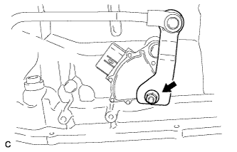
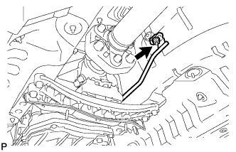
Install the transmission control shaft lever with the spring washer and nut.
- Torque:
- 16 N*m { 160 kgf*cm, 12 ft.*lbf }
-
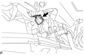
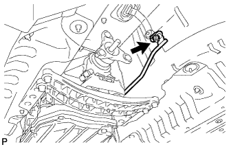
Connect the park/neutral position switch assembly connector.
-
-
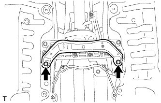
INSTALL REAR ENGINE MOUNTING MEMBER
-
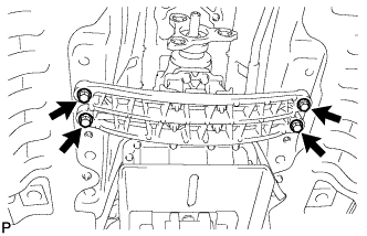
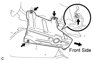
Install the rear engine mounting member with the 4 bolts.
- Torque:
- 35 N*m { 354 kgf*cm, 26 ft.*lbf }
-
-
CONNECT FLOOR SHIFT GEAR SHIFTING ROD SUB-ASSEMBLY
-
Temporarily install the floor shift gear shifting rod sub-assembly with the nut.
-
-
ADJUST SHIFT LEVER POSITION
-
Remove the nut and disconnect the shifting rod.
-
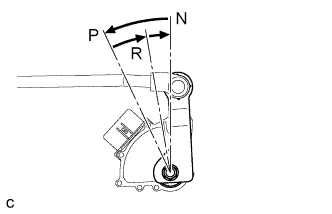
Turn the control shaft lever of the park/neutral position switch counterclockwise until it stops, and turn it clockwise 2 notches to set it to N.
-
Move the shift lever to N and tighten the nut while lightly pushing the lever toward R.
- Torque:
- 13 N*m { 130 kgf*cm, 9 ft.*lbf }
Note
Do not push the shift lever too hard.
-
Check that the shift lever moves smoothly and the shift lever and gear operate correctly Click here.
-
-
INSTALL PROPELLER SHAFT WITH CENTER BEARING ASSEMBLY
-
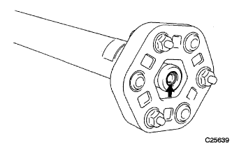
Apply grease to the flexible coupling centering bushings.
Grease Molybdenum disulphide lithium base NLGI No. 2 -
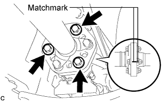
Align the matchmarks on the transmission companion flange and flexible coupling.
-
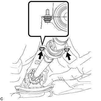
Install and tighten the 3 bolts, 3 washers and 3 nuts.
- Torque:
- 79 N*m { 805 kgf*cm, 58 ft.*lbf }
Note
Be careful not to damage the flexible coupling centering bushings.
Tech Tips
The bolts should be installed from the propeller shaft side.
-
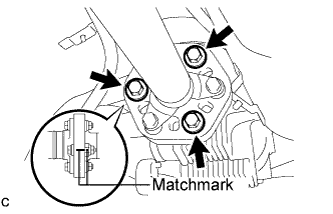
Align the matchmarks on the differential companion flange and flexible coupling.
-
Install and tighten the 3 bolts, 3 washers and 3 nuts.
- Torque:
- 79 N*m { 805 kgf*cm, 58 ft.*lbf }
Note
Be careful not to damage the flexible coupling centering bushings.
Tech Tips
The bolts should be installed from the propeller shaft side.
-
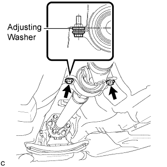
Temporarily install the 2 center support bearing set bolts with the adjusting center support bearing washers.
Tech Tips
Reuse any removed adjusting washers.
-
-
FULLY TIGHTEN NO. 1 CENTER SUPPORT BEARING ASSEMBLY
-
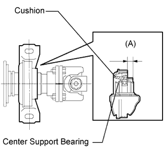
Adjust the dimension between the edge surface of the center support bearing and the edge surface of the cushion to 11.5 to 13.5 mm (0.4528 to 0.5315 in.) respectively as shown in the illustration.
(A) 11.5 to 13.5 mm (0.4528 to 0.5315 in.) -
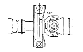
Check that the center line of the bracket is perpendicular to the shaft axial direction.
-
Tighten the 2 bolts.
- Torque:
- 49 N*m { 500 kgf*cm, 36 ft.*lbf }
-
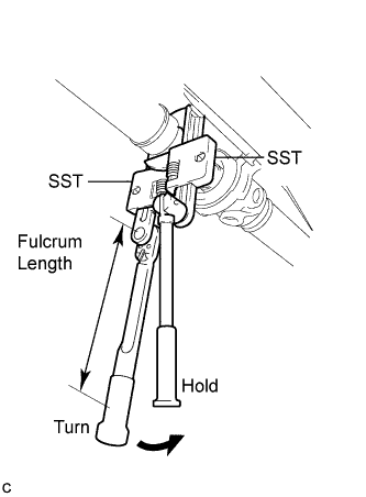
Using SST, tighten the adjusting nut.
- SST
- 09922-10010
- Torque:
- without SST
- 69 N*m { 700 kgf*cm, 51 ft.*lbf }
- with SST
- 51 N*m { 520 kgf*cm, 38 ft.*lbf }
Tech Tips
-
Use a torque wrench with a fulcrum length of 345 mm (13.6 in.).
-
Use 2 of the same SST.
-
-
INSPECT AND ADJUST NO. 2 AND NO. 3 JOINT ANGLE
-
Stabilize the propeller shaft and differential.
-
Turn the propeller shaft several times by hand to stabilize the center support bearing.
-
-
Check both the No. 2 and No. 3 joint angles.
-
Using SST, measure the installation angle of the intermediate shaft and propeller shaft.
- SST
- 09370-50010
Tech Tips
The SST should be set directly on the bottom of the shaft.
-
Using SST, measure the installation angle of the differential.
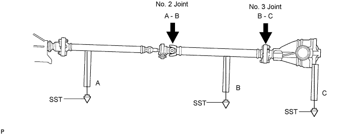
- SST
- 09370-50010
Tech Tips
Measure the installation angle by placing SST in the positions shown in the illustration.
-
Calculate the No. 2 joint angle.
No. 2 joint angle A - B = -0°19' to -1°19' A Intermediate shaft installation angle B Propeller shaft installation angle -
Calculate the No. 3 joint angle.
No. 3 joint angle B - C = 1°07' to 2°07' B Propeller shaft installation angle C Differential installation angle Tech Tips
If the measured angle is not within the specified range, adjust it with the center support bearing washers.
-
-
Adjust the No. 2 joint angle.
-
Select the center support bearing washers for adjustment.
Adjustment Washer Thickness mm (in.) 2.0 (0.0787) 4.5 (0.1772) 6.5 (0.2559) 9.0 (0.3543) 11.0 (0.4331) Note
The 2 washers should be the same thickness.
-
-
-
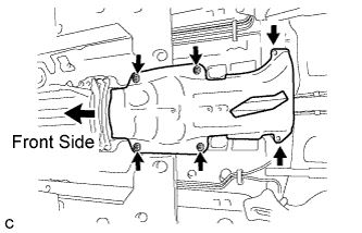
INSTALL OUTSIDE AIR GUIDE PLATE RH
-
Install the outside air guide plate RH with the 4 nuts.
- Torque:
- 5.4 N*m { 55 kgf*cm, 48 in.*lbf }
-
-
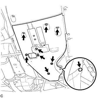
INSTALL FRONT NO. 1 FLOOR HEAT INSULATOR
-
Install the front No. 1 floor heat insulator with the 4 nuts and 2 bolts.
- Torque:
- Nut
- 5.4 N*m { 55 kgf*cm, 48 in.*lbf }
- Bolt
- 19 N*m { 194 kgf*cm, 14 ft.*lbf }
-
-
INSTALL FRONT EXHAUST PIPE ASSEMBLY
-
Install 2 new gaskets to the exhaust manifold RH and exhaust manifold LH.
-
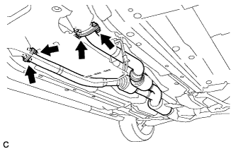
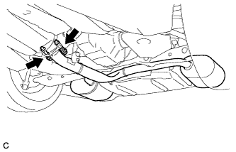
Install the front exhaust pipe assembly with 4 new bolts and 4 new nuts.
- Torque:
- 39 N*m { 398 kgf*cm, 29 ft.*lbf }
-
-
CONNECT HEATED OXYGEN SENSOR
-
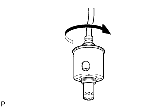
Rotate the heated oxygen sensors 4 times counterclockwise, and then install them to the front exhaust pipe assembly by hand.
-
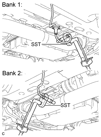
Using SST, tighten the 2 heated oxygen sensors.
- SST
- 09224-00010
- Torque:
- with SST
- 40 N*m { 408 kgf*cm, 30 ft.*lbf }
- without SST
- 44 N*m { 449 kgf*cm, 32 ft.*lbf }
Tech Tips
-
Use a torque wrench with a fulcrum length of 30 cm (11.8 in.). If the fulcrum length is not as specified, calculate the torque value based on the specification for when SST is not used Click here.
-
Make sure that SST and the wrench are connected in a straight line.
-
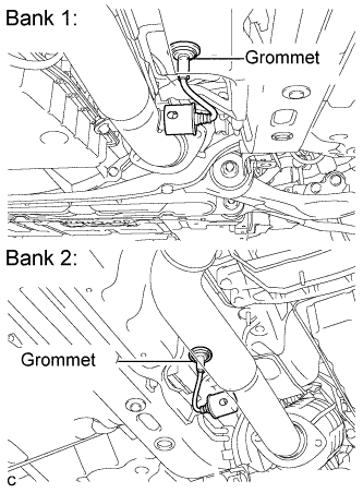
Connect the 2 grommets to the floor panel.
-
-
INSTALL TAIL EXHAUST PIPE ASSEMBLY
-
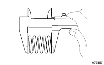
Using a vernier caliper, measure the free length of the compression springs.
Minimum length 41.5 mm (1.634 in.) If the free length is less than the minimum, replace the compression spring.
-
Fully insert a new gasket to the front exhaust pipe assembly.
-
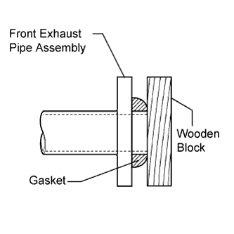
Using a plastic hammer and wooden block, tap in the new gasket until its surface is flush with the front exhaust pipe assembly.
Note
-
Be sure to install the gasket in the correct direction.
-
Do not reuse the gasket.
-
Do not damage the gasket.
-
Do not push in the gasket by using the exhaust pipe when connecting it.
-
-
Connect the tail exhaust pipe assembly to the 6 exhaust pipe supports.
-
Install the tail exhaust pipe assembly with the 2 bolts and 2 compression springs.
- Torque:
- 43 N*m { 440 kgf*cm, 32 ft.*lbf }
-
-
INSTALL FRONT CENTER FLOOR BRACE
-
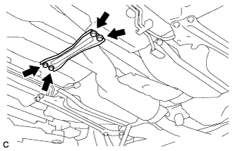
Install the front center floor brace with the 4 bolts.
- Torque:
- 7.4 N*m { 76 kgf*cm, 66 in.*lbf }
-
-
INSTALL REAR NO. 1 FLOOR PANEL BRACE
-
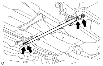
Install the rear No. 1 floor panel brace with the 4 bolts.
- Torque:
- 19 N*m { 194 kgf*cm, 14 ft.*lbf }
-
-
INSTALL ENGINE UNDER COVER AIR GUIDE BRACKET
-
Install the engine under cover air guide bracket with the 2 bolts.
- Torque:
- 26 N*m { 265 kgf*cm, 19 ft.*lbf }
-
-
INSPECT PARK/NEUTRAL POSITION SWITCH ASSEMBLY
-
Inspect the park/neutral position switch assembly Click here.
-
-
INSPECT SHIFT LEVER POSITION
-
When shifting from P to R with the engine switch on (IG) and the brake pedal depressed, make sure that the shift lever moves smoothly and moves correctly into the position.
-
Check that the shift lever does not stop when moving the shift lever from R to P, and check that the shift lever does not stick when moving the shift lever from D to M.
-
Start the engine and make sure that the vehicle moves forward when shifting from N to D and moves rearward when shifting to R.
If an operation cannot be done as specified, inspect the park/neutral position switch assembly and check the shift lever assembly installation condition.
-
-
INSPECT FOR EXHAUST GAS LEAK
-
INSTALL NO. 2 FLOOR UNDER COVER
-
Install the No. 2 floor under cover with the 6 clips and 3 grommets.
-
-
INSTALL NO. 1 FLOOR UNDER COVER
-
Install the No. 1 floor under cover with the 5 clips and 3 grommets.
-
-
INSTALL NO. 2 ENGINE UNDER COVER