FUEL INJECTOR (for Direct Injection) REMOVAL

-
PRECAUTION
CAUTION:
-
Do not smoke or work near an open flame when handling the fuel system.
-
Keep gasoline away from rubber or leather parts.
-
Do not allow fuel to spray when removing the pipe between the high pressure side fuel pump assembly and the fuel injector assembly. The fuel in the pipe is highly pressurized.
-
-
DISCHARGE FUEL SYSTEM PRESSURE
-
Discharge fuel system pressure Click here.
-
-
DISCONNECT CABLE FROM NEGATIVE BATTERY TERMINAL
Note
When disconnecting the cable, some systems need to be initialized after the cable is reconnected Click here.
-
REMOVE INTAKE AIR SURGE TANK ASSEMBLY
-
Remove the intake air surge tank assembly Click here.
-
-
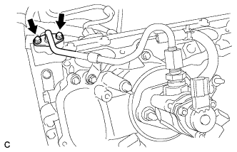
REMOVE NO. 1 FUEL HOSE
-
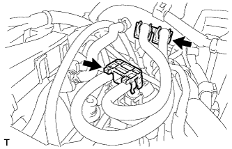
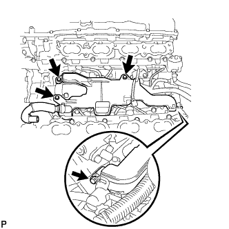
Remove the 2 fuel pipe clamps.
-
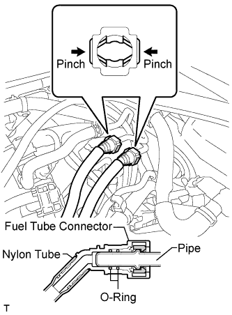
Pinch the 2 fuel tube connector and then pull out the No. 1 fuel hose.
Note
-
Check for any dirt and foreign matter contamination in the pipe and around the connector. Clean if necessary. Foreign matter may damage the O-rings or cause leaks in the seal between the pipe and connector.
-
Do not use any tools to separate the pipe and connector.
-
Do not forcefully bend or twist the nylon tube.
-
Check for any dirt and foreign matter on the pipe seal surface. Clean if necessary.
-
Put the pipe and connector ends in plastic bags to prevent damage and dirt contamination.
-
If the pipe and connector are stuck together, pinch the tube between your fingers and turn it carefully to free it. Then disconnect the hose.
-
-
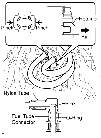
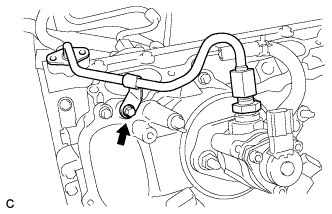
Lift up the retainer to release its lock.
-
Pinch the 2 fuel tube connectors and then pull out the No. 1 fuel hose.
Note
-
Check for any dirt and foreign matter contamination in the pipe and around the connector. Clean if necessary. Foreign matter may damage the O-rings or cause leaks in the seal between the pipe and connector.
-
Do not use any tools to separate the pipe and connector.
-
Do not forcefully bend or twist the nylon tube.
-
Check for any dirt and foreign matter on the pipe seal surface. Clean if necessary.
-
Put the pipe and connector ends in plastic bags to prevent damage and dirt contamination.
-
If the pipe and connector are stuck together, pinch the tube between your fingers and turn it carefully to free it. Then disconnect the hose.
-
-
-
SEPARATE ENGINE WIRE
-
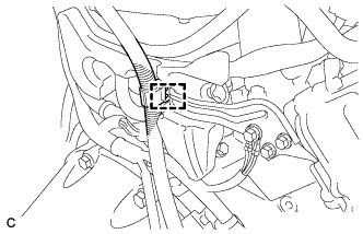
Disconnect the harness clamp and then separate the engine wire.
-
-
REMOVE NO. 3 COVER SUB-ASSEMBLY
-
Remove the bolt and separate the engine wire.
-
Remove the 2 bolts and bracket.
-
Remove the 2 clips and No. 3 cover sub-assembly.
-
-
REMOVE FUEL PRESSURE PULSATION DAMPER ASSEMBLY (for Direct Injection)
-
Remove the fuel pressure pulsation damper assembly and No. 1 fuel pipe sub-assembly Click here.
-
-
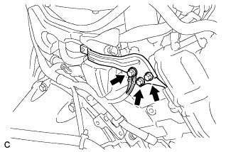
REMOVE NO. 3 FUEL PIPE SUB-ASSEMBLY
-
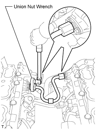
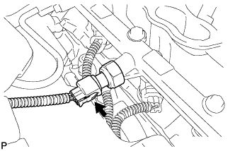
Remove the high pressure side fuel pump assembly connector.
-
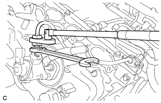
Secure the union bolt on the fuel pump assembly side in place with a 21 mm wrench. Using a 19 mm union nut wrench, loosen the union nut and disconnect the fuel pipe from the fuel pump assembly.
Note
Do not loosen the union bolt on the fuel pump side. If the union bolt is accidentally loosened, replace the fuel pump assembly.
-
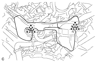
Remove the 2 bolts on the delivery pipe side and remove the No. 3 fuel pipe sub-assembly.
-
-
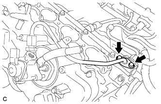
REMOVE NO. 2 FUEL PIPE SUB-ASSEMBLY
-
Remove the high pressure side fuel pump assembly connector.
-
Secure the union bolt on the fuel pump assembly side in place with a 21 mm wrench. Using a 19 mm union nut wrench, loosen the union nut and disconnect the fuel pipe from the fuel pump assembly.
Note
Do not loosen the union bolt on the fuel pump side. If the union bolt is accidentally loosened, replace the fuel pump assembly.
Tech Tips
Use the same procedure as for the bank 1 side.
-
Remove the 2 bolts on the delivery pipe side and separate the No. 2 fuel pipe sub-assembly.
-
Remove the bolt and No. 2 fuel pipe sub-assembly.
-
-
REMOVE NO. 1 ENGINE COVER SUB-ASSEMBLY
-
Remove the No. 1 engine cover sub-assembly.
-
-
REMOVE NO. 2 ENGINE COVER SUB-ASSEMBLY LH
-
Remove the No. 2 engine cover sub-assembly LH.
-
-
REMOVE NO. 4 FUEL PIPE SUB-ASSEMBLY
-
Using a 19 mm union nut wrench, remove the No. 4 fuel pipe sub-assembly.
-
-
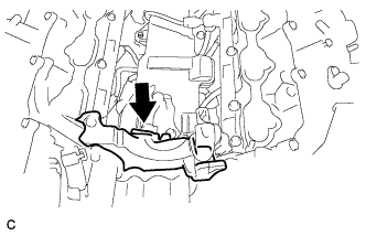
REMOVE SEPARATOR CASE
-
Disconnect the fuel pressure sensor connector.
-
Remove the 4 bolts and separator case from the cylinder head.
-
-
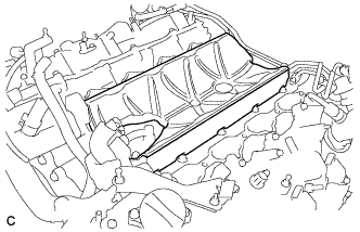
REMOVE NO. 2 FUEL DELIVERY PIPE (for Direct Injection)
-
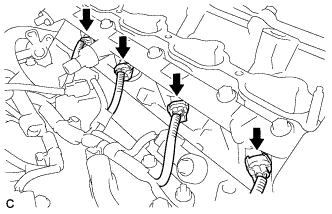
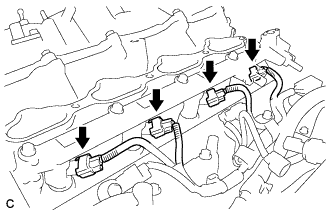
Disconnect the 4 injector connectors.
-
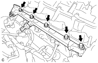
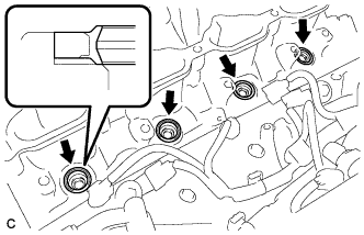
Remove the 5 bolts and the No. 2 fuel delivery pipe from the cylinder head.
Note
-
Be extremely careful not to touch or strike the tips of the injectors.
-
Pull the No. 2 fuel delivery pipe straight without tilting it.
-
-
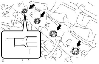
Remove the 4 injector vibration insulators from the cylinder head.
-
-
REMOVE FUEL DELIVERY PIPE (for Direct Injection)
-
Disconnect the 4 injector connectors.
-
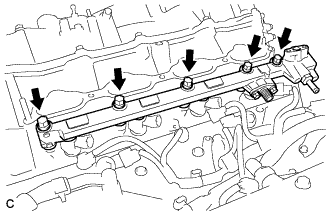
Remove the 5 bolts and the fuel delivery pipe from the cylinder head.
Note
-
Be extremely careful not to touch or strike the tips of the injectors.
-
Pull the fuel delivery pipe straight without tilting it.
-
-
Remove the 4 injector vibration insulators from the cylinder head.
-
-
REMOVE FUEL INJECTOR ASSEMBLY (for Direct Injection)
-
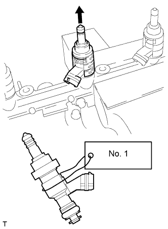
Secure the delivery pipe between aluminum plates in a vise and pull the fuel injector assembly out in a straight line.
Note
-
Pull the fuel injector assembly straight out to avoid damage to the seal surface of the fuel delivery pipe and No.2 fuel delivery pipe O-ring.
-
For reinstallation, attach a tag or label to the injector shaft.
-
-
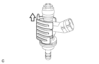
Remove the nozzle holder clamp from the injector assembly.
-
Remove the O-ring, backup rings (No. 1, No. 2 and No. 3) and E-ring from the fuel injector.
-
-
REMOVE FUEL INJECTOR SEAL
-
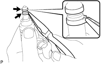
Using the tips of needle-nose pliers, pinch and pull one of the 2 fuel injector seals at several points to stretch it. Repeat this for the other fuel injector seal.
Note
-
Excessively pinching the fuel injector seal may damage the groove of the fuel injector assembly.
-
If an fuel injector assembly is dropped or the tip of an fuel injector assembly is struck, replace it with a new one.
-
-
Remove the 2 fuel injector seals from the fuel injector assembly.
-
-
REMOVE FUEL PIPE SUPPORT SUB-ASSEMBLY
-
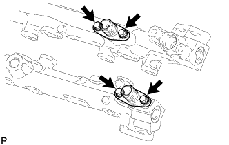
Remove the 4 bolts and 2 fuel pipe support sub-assemblies.
-
Remove the 2 O-rings, 2 No. 1 backup rings, 2 No. 2 backup rings and 2 E-rings from the 2 fuel pipe support sub-assemblies.
-
-
REMOVE FUEL DELIVERY PIPE PLUG
-
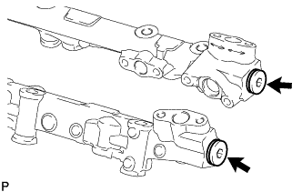
Using a 6 mm hexagon socket wrench, remove the 2 fuel delivery pipe plugs and 2 gaskets from the fuel delivery pipe and No. 2 fuel delivery pipe.
-