METER / GAUGE SYSTEM Speed Signal Circuit
DESCRIPTION
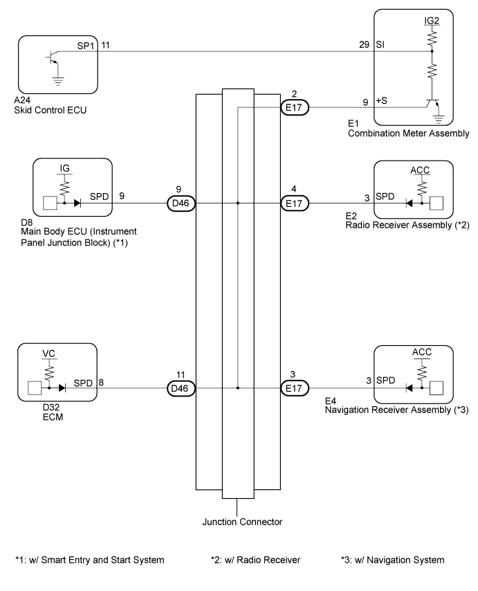
The meter CPU receives vehicle speed signals from this circuit. The vehicle speed sensor detects the voltage that varies according to the vehicle speed. The skid control ECU supplies power to the vehicle speed sensor. The skid control ECU detects vehicle speed signals based on the pulses of the voltage. The skid control ECU transmits vehicle speed signals as pulses to the meter CPU. A voltage of 12 V is output from the combination meter assembly and then input to the skid control ECU. The signal is changed to a pulse signal at the transistor in the combination meter assembly.
A voltage of 12 V or 5 V is output from each ECU or relay and then input to the combination meter assembly.
Each ECU controls the respective system based on the pulse signal.
Tech Tips
This circuit is used for another system, and is not used for speedometer operation.
WIRING DIAGRAM
INSPECTION PROCEDURE
PROCEDURE
-
INSPECT ECU TERMINAL VOLTAGE (INPUT VOLTAGE)
-
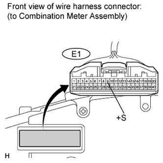
Disconnect the E1 connector.
-
Measure the voltage according to the value(s) in the table below.
Standard voltage Tester Connection Condition Specified Condition E1-9 (+S) - Body ground Ignition switch on (IG) 4.5 to 14 V Tech Tips
If any of the ECUs specified in the wiring diagram supply power to the combination meter, the combination meter will output a waveform.
NG 
CHECK HARNESS AND CONNECTOR (COMBINATION METER - JUNCTION CONNECTOR) Click here
OK 
-
-
INSPECT COMBINATION METER (OUTPUT VOLTAGE)
-
Reconnect the E1 connector.
-
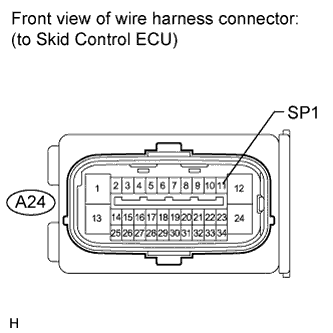
Disconnect the A24 connector.
-
Measure the voltage according to the value(s) in the table below.
Standard voltage Tester Connection Condition Specified Condition A24-11 (SP1) - Body ground Ignition switch on (IG) 11 to 14 V
NG
CHECK HARNESS AND CONNECTOR (COMBINATION METER - SKID CONTROL ECU) Click here
OK
-
-
INSPECT SKID CONTROL ECU (INPUT WAVEFORM)
-
Check the input waveform.
-
Reconnect the A24 connector.
-
Remove the combination meter assembly with the connector(s) still connected.
-
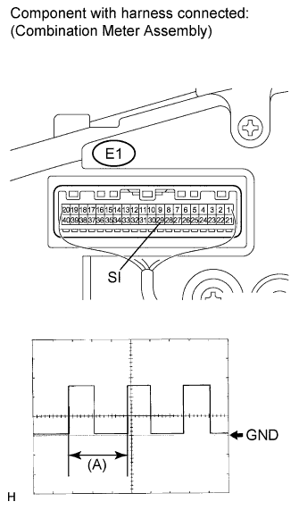
Connect an oscilloscope to terminal E1-29 (SI) and body ground.
-
Ignition switch on (IG).
-
Turn the wheel slowly.
-
Check the signal waveform according to the condition(s) in the table below.
Item Condition Tool setting 5 V/DIV., 20 ms./DIV. Vehicle condition Driving at approx. 20 km/h (12 mph) OK The waveform is displayed as shown in the illustration. Tech Tips
When the system is functioning normally, one wheel revolution generates 4 pulses. As the vehicle speed increases, the width indicated by (A) in the illustration narrows.
-
NG 
REPLACE SKID CONTROL ECU Click here
OK 
REPLACE COMBINATION METER Click here
-
-
CHECK HARNESS AND CONNECTOR (COMBINATION METER - JUNCTION CONNECTOR)
-
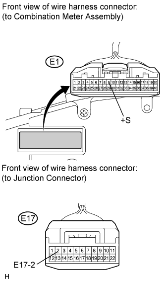
Disconnect the junction connector.
-
Measure the resistance according to the value(s) in the table below.
Standard resistance Tester Connection Condition Specified Condition E1-9 (+S) - E17-2 Always Below 1 Ω E1-9 (+S) - Body ground Always 10 kΩ or higher
NG
REPAIR OR REPLACE HARNESS OR CONNECTOR
OK
-
-
CHECK HARNESS AND CONNECTOR (JUNCTION CONNECTOR)
-
Inspect for a short in the circuit that is connected to the junction connector shown in the wiring diagram.
Tech Tips
If voltage is not present, the circuit (ECU) is possibly malfunctioning. This is the circuit that will be diagnosed by following the A step that follows.
-
Disconnect the junction connectors.
-
Measure the voltage according to the value(s) in the table below.
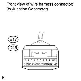
Standard voltage Tester Connection Condition Specified Condition E17-3 (*2)- Body ground Ignition switch on (IG) 4.5 to 14 V E17-4 - Body ground Ignition switch on (IG) 4.5 to 14 V D46-9 (*1) - Body ground Ignition switch on (IG) 4.5 to 14 V D46-11 - Body ground Ignition switch on (IG) 4.5 to 14 V *1: w/ Smart Entry and Start System
*2: w/ Navigation System
Result Result Proceed to Voltage is not present in one circuit. A Voltage is present in all the circuits. B
-
B
REPLACE JUNCTION CONNECTOR
A
-
-
SYSTEM CHECK
-
Select the circuit in which is not present voltage in step 5.
Result Tester Connection System that uses the circuit Proceed to D46-9 (*1) - Body ground Smart entry and start system A D46-11 - Body ground SFI system B E17-4 - Body ground Audio/visual system C E17-3 (*2) - Body ground Navigation system D *1: w/ Smart Entry and Start System
*2: w/ Navigation System
B
CHECK HARNESS AND CONNECTOR (ECM CIRCUIT) Click here
C
CHECK HARNESS AND CONNECTOR (RADIO RECEIVER CIRCUIT) Click here
D
CHECK HARNESS AND CONNECTOR (NAVIGATION RECEIVER CIRCUIT) Click here
A
-
-
CHECK HARNESS AND CONNECTOR (MAIN BODY ECU CIRCUIT)
-
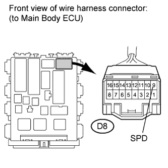
Disconnect the D8 (*) connector.
-
Measure the resistance according to the value(s) in the table below.
Standard resistance Tester Connection Condition Specified Condition D8-9 (SPD) (*) - Body ground Always 10 kΩ or higher *: w/ Smart Entry and Start System
NG
REPAIR OR REPLACE HARNESS OR CONNECTOR
OK
REPLACE MAIN BODY ECU
-
-
CHECK HARNESS AND CONNECTOR (ECM CIRCUIT)
-
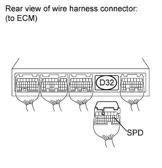
Disconnect the D32 connector.
-
Measure the resistance according to the value(s) in the table below.
Standard resistance Tester Connection Condition Specified Condition D32-8 (SPD) - Body ground Always 10 kΩ or higher
NG
REPAIR OR REPLACE HARNESS OR CONNECTOR
OK
REPLACE ECM Click here
-
-
CHECK HARNESS AND CONNECTOR (RADIO RECEIVER CIRCUIT)
-
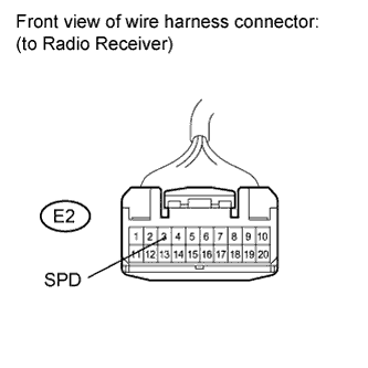
Disconnect the E2 connector.
-
Measure the resistance according to the value(s) in the table below.
Standard resistance Tester Connection Condition Specified Condition E2-3 (SPD) - Body ground Always 10 kΩ or higher
NG
REPAIR OR REPLACE HARNESS OR CONNECTOR
OK
REPLACE RADIO RECEIVER Click here
-
-
CHECK HARNESS AND CONNECTOR (NAVIGATION RECEIVER CIRCUIT)
-
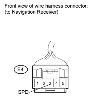
Disconnect the E4 (*) connector.
-
Measure the resistance according to the value(s) in the table below.
Standard resistance Tester Connection Condition Specified Condition E4-3 (SPD) (*) - Body ground Always 10 kΩ or higher *: w/ Navigation System
NG
REPAIR OR REPLACE HARNESS OR CONNECTOR
OK
REPLACE NAVIGATION RECEIVER Click here
-
-
CHECK HARNESS AND CONNECTOR (COMBINATION METER - SKID CONTROL ECU)
-
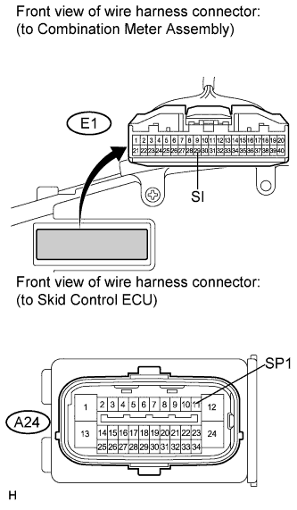
Disconnect the E1 connector.
-
Measure the resistance according to the value(s) in the table below.
Standard resistance Tester Connection Condition Specified Condition A24-11 (SP1) - E1-29 (SI) Always Below 1 Ω A24-11 (SP1) - Body ground Always 10 kΩ or higher
NG
REPAIR OR REPLACE HARNESS OR CONNECTOR
OK
REPLACE COMBINATION METER Click here
-