SLIDING ROOF HOUSING INSTALLATION

-
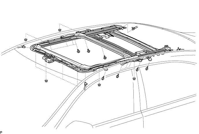
INSTALL SLIDING ROOF HOUSING SUB-ASSEMBLY
-
Temporarily install the sliding roof housing sub-assembly with the 12 bolts (vehicle body side) and 8 nuts.
-
Tighten the 8 nuts.
- Torque:
- 5.5 N*m { 56 kgf*cm, 49 in.*lbf }
-
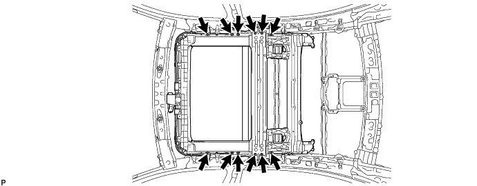
Tighten the 12 bolts.
- Torque:
- 8.0 N*m { 82 kgf*cm, 71 in.*lbf }
-
Tighten the 12 bolts.
- Torque:
- 5.4 N*m { 55 kgf*cm, 48 in.*lbf }
-
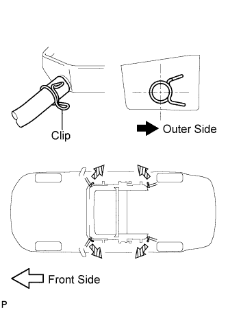
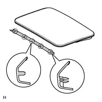
Connect the 4 drain hoses.
Note
The clip must face toward the outside of the vehicle and also be above the lower surface of the sliding roof housing when installing the drain hoses.
-
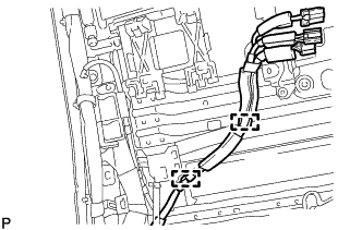
w/ Rear Seat Entertainment System:
Attach the 2 clamps to connect the wire harness.
-
-
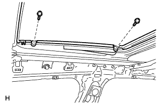
INSTALL REAR SLIDING ROOF HOUSING MOUNTING BRACKET LH
-
Install the rear sliding roof housing mounting bracket LH with the 2 bolts.
- Torque:
- 8.0 N*m { 82 kgf*cm, 71 in.*lbf }
-
Attach the clamp to connect the curtain shield airbag wire harness.
-
-
INSTALL REAR SLIDING ROOF HOUSING MOUNTING BRACKET RH
Tech Tips
Use the same procedure described for the LH side.
-
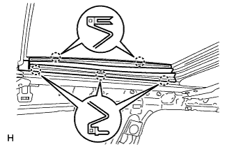
INSTALL SLIDING ROOF PANEL PLATE
-
Attach the 2 guides to install the 2 sliding roof panel plates with the 4 bolts.
-
-
INSTALL FRONT SLIDING ROOF GARNISH
-
Attach the 5 claws to install the front sliding roof garnish.
-
-
INSTALL SLIDING ROOF GLASS SUB-ASSEMBLY
-
Using a T25 "TORX" driver, temporarily install the sliding roof glass sub-assembly with the 4 screws.
-
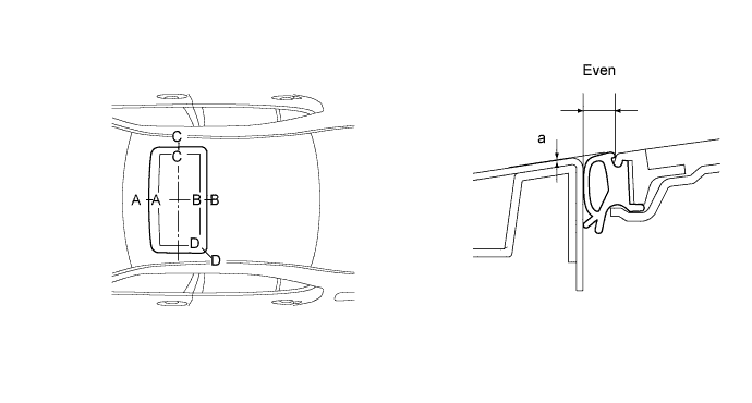
Perform a level check.
-
Check the difference in the level for "a" between the roof panel and the upper surface of the weatherstrip when the sliding roof glass sub-assembly is fully closed.
Standard Area Measurement A - A -2.0 to +1.0 mm (-0.079 to +0.039 in.) B - B -1.0 to +2.0 mm (-0.039 to +0.079 in.) C - C -1.5 to +1.5 mm (-0.059 to +0.059 in.) D - D -1.0 to +1.5 mm (-0.039 to +0.059 in.) Tech Tips
"+" represents the condition that the glass is above the panel level. "-" represents the condition that the glass is below the panel level.
-
Perform a gap check.
Check the gap between the roof panel and roof glass.
Note
The gap must be even all around.
-
-
Using a T25 "TORX" driver, tighten the 4 screws.
- Torque:
- 5.5 N*m { 56 kgf*cm, 49 in.*lbf }
-
-
CHECK FOR WATER LEAKS
-
After adjusting the sliding roof glass sub-assembly, check for water leaks.
-
If there are any leaks, readjust the sliding roof glass sub-assembly.
-
-
INSTALL SLIDING ROOF SIDE GARNISH LH
-
Attach the 5 claws to install the sliding roof side garnish LH.
-
-
INSTALL SLIDING ROOF SIDE GARNISH RH
Tech Tips
Use the same procedure described for the LH side.
-
INSTALL NO. 1 ROOF SIDE AIR DUCT LH (w/ Rear Cooler)
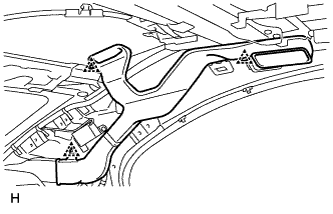
-
Install the No. 1 roof side air duct LH with the 3 clips.
-
-
INSTALL NO. 1 ROOF SIDE AIR DUCT RH (w/ Rear Cooler)
Tech Tips
Use the same procedure described for the LH side.
-
INSTALL CURTAIN SHIELD AIRBAG ASSEMBLY LH
-
INSTALL CURTAIN SHIELD AIRBAG ASSEMBLY RH
Tech Tips
Use the same procedure described for the LH side.
-
INSTALL ROOF HEADLINING ASSEMBLY (for Long Body)
-
INSTALL ROOF HEADLINING ASSEMBLY (for Standard Body)
-
CONNECT CABLE TO NEGATIVE BATTERY TERMINAL
Note
When disconnecting the cable, some systems need to be initialized after the cable is reconnected Click here.
-
INSTALL COWL TOP VENTILATOR LOUVER RH
-

for LHD:
Install the 6 clips and cowl top ventilator louver RH.
Note
If the cowl top ventilator louver RH is not properly installed, water may leak into the engine room and cause malfunctions. Therefore, make sure the cowl top ventilator louver RH is installed properly.
-

for RHD:
Install the 6 clips and cowl top ventilator louver LH.
Note
If the cowl top ventilator louver LH is not properly installed, water may leak into the engine room and cause malfunctions. Therefore, make sure the cowl top ventilator louver LH is installed properly.
-
-
CHECK SRS WARNING LIGHT