LUGGAGE COMPARTMENT DOOR OPENER OUTER SWITCH INSTALLATION

-
INSTALL LUGGAGE ELECTRICAL KEY SWITCH
-
Install the television camera assembly to the luggage electrical key switch with the 2 screws.
-
Connect the connector.
-
Connect the sub-wire harness connector.
-
-
INSTALL LUGGAGE COMPARTMENT DOOR OUTSIDE GARNISH SUB-ASSEMBLY
-
Attach the 6 clips to install the luggage compartment door outside garnish.
-
Install the 6 screws.
-
-
INSTALL NO. 3 LUGGAGE COMPARTMENT DOOR OUTSIDE GARNISH
-
Attach the 4 claws to install the No. 3 luggage compartment door outside garnish.
-
-
INSTALL REAR LIGHT ASSEMBLY LH
-
w/o Rear Fog Light:
-
Install the rear light assembly LH with the 2 nuts and 2 cap nuts.
- Torque:
- 4.5 N*m { 46 kgf*cm, 40 in.*lbf }
-
Connect the connector.
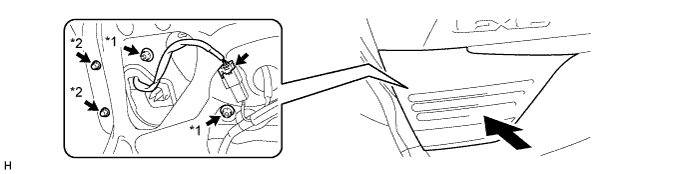
Text in Illustration *1 Nut *2 Cap Nut
-
-
w/ Rear Fog Light:
-
Install the rear light assembly LH with the 2 nuts and 2 cap nuts.
- Torque:
- 4.5 N*m { 46 kgf*cm, 40 in.*lbf }
-
Connect the connector.
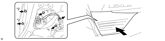
Text in Illustration *1 Nut *2 Cap Nut
-
-
-
INSTALL REAR LIGHT ASSEMBLY RH
Tech Tips
Use the same procedure described for the LH side.
-
INSTALL BACK DOOR TRIM COVER
-
Attache the 10 clips to install the back door trim cover.
-
Install the 4 clips.
-
-
INSTALL LUGGAGE COMPARTMENT DOOR HINGE COVER RH
Tech Tips
Use the same procedure described for the LH side.
-
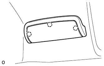
INSTALL LUGGAGE COMPARTMENT DOOR HINGE COVER LH
-
Install the luggage compartment door hinge cover LH with the 3 clips.
-
-
INSTALL REAR COMBINATION LIGHT SERVICE COVER LH
-
Attach the 3 claws to install the rear combination light service cover LH.
-
-
INSTALL REAR COMBINATION LIGHT SERVICE COVER RH
Tech Tips
Use the same procedure described for the LH side.
-
INSTALL NO. 2 COURTESY LIGHT ASSEMBLY
-
Connect the connector.
-
Attach the 2 claws to install the No. 2 courtesy light assembly.
-
-
INSTALL SWITCH BEZEL
-
Attach the 2 claws to install the switch bezel.
-
-
INSTALL LUGGAGE COMPARTMENT DOOR ASSIST GRIP
-
Install the luggage compartment door assist grip with the 2 screws.
-
Attach the 3 claws.
-
-
CONNECT CABLE TO NEGATIVE BATTERY TERMINAL
Note
When disconnecting the cable, some systems need to be initialized after the cable is reconnected Click here.
-
INSTALL COWL TOP VENTILATOR LOUVER RH
-

Install the 6 clips and cowl top ventilator louver RH.
Note
Be sure to install the cowl top ventilator louver RH properly. If it is not installed properly, water may enter the engine room and cause malfunctions.
-
-
ADJUST REAR TELEVISION CAMERA ASSEMBLY (w/ Parking Assist Monitor System)