BACK WINDOW GLASS REMOVAL

Tech Tips
When removing the moulding, heat the vehicle body and moulding using a heat light.
| Heating temperature | ||||||
|---|---|---|---|---|---|---|
|
Note
Do not heat the vehicle body and moulding excessively.
-
PRECAUTION
Note
After turning the engine switch off, waiting time may be required before disconnecting the cable from the battery terminal. Therefore, make sure to read the disconnecting the cable from the battery terminal notice before proceeding with work. Click here.
-
REMOVE COWL TOP VENTILATOR LOUVER RH
-

Remove the 6 clips and cowl top ventilator louver RH.
-
-
DISCONNECT CABLE FROM NEGATIVE BATTERY TERMINAL
CAUTION:
Wait at least 90 seconds after disconnecting the cable from the negative (-) battery terminal to prevent airbag and seat belt pretensioner activation.
Note
When disconnecting the cable, some systems need to be initialized after the cable is reconnected Click here.
-
REMOVE REAR SEAT ASSEMBLY
-
for Power Seat:
Remove the rear seat Click here.
-
for Ottoman:
Remove the rear seat Click here.
-
for Fixed Seat Type:
Remove the rear seat Click here.
-
-
REMOVE REAR DOOR SCUFF PLATE LH
-
for Standard Body:
Remove the rear door scuff plate Click here.
-
for Long Body:
Remove the rear door scuff plate Click here.
-
-
REMOVE REAR DOOR SCUFF PLATE RH
-
for Standard Body:
Remove the rear door scuff plate Click here.
-
for Long Body:
Remove the rear door scuff plate Click here.
-
-
REMOVE REAR SEAT SIDE GARNISH LH
-
Detach the 6 claws and remove the rear seat side garnish LH.
-
-
REMOVE REAR SEAT SIDE GARNISH RH
Tech Tips
Use the same procedure described for the LH side.
-
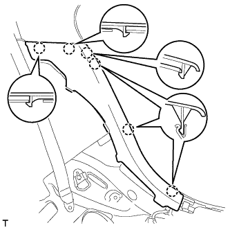
REMOVE ROOF SIDE GARNISH INNER LH
Text in Illustration *1 Clip A
-
Pull the inner roof side garnish LH away from the body to detach the 4 clips (do not detach clip A).
-
Detach the 2 claws of the guide, and pull the inner roof side garnish LH in the direction of the arrow to remove it.
Tech Tips
Clip A remains attached to the body.
-
Remove clip A from the vehicle body.
-
-
REMOVE ROOF SIDE GARNISH INNER RH
Tech Tips
Use the same procedure described for the LH side.
-
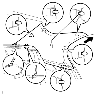
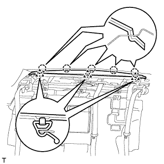
REMOVE PACKAGE TRAY TRIM PANEL ASSEMBLY
-
except 4-Passenger with Ottoman:
Using a moulding remover D, detach the 4 claws and remove the 3 belt guides.
-
for 4-Passenger with Ottoman:
Using a moulding remover D, detach the 4 claws and remove the 2 belt guides.
-
except 4-Passenger with Ottoman:
Detach the 2 clips of the package tray trim panel. Then pass the 3 rear seat belt floor anchors through the package tray trim panel assembly.
-
for 4-Passenger with Ottoman:
Detach the 2 clips of the package tray trim panel. Then pass the 2 rear seat belt floor anchors through the package tray trim panel assembly.
-
w/o Rear Cooler:
Remove the package tray trim panel assembly.
-
w/ Rear Cooler:
Disconnect the solar sensor connector and remove the package tray trim panel assembly.
-
-
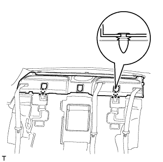
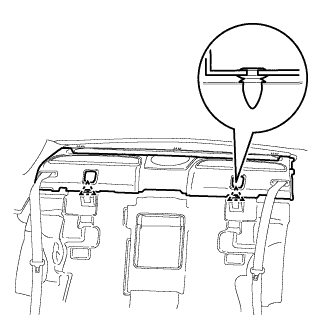
REMOVE NO. 2 PACKAGE TRAY TRIM PANEL ASSEMBLY
-
Detach the 5 claws and 3 clips, and remove the No. 2 package tray trim panel assembly.
-
-
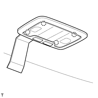
REMOVE ROOF CONSOLE BOX ASSEMBLY (w/ Rear Seat Entertainment System)
-
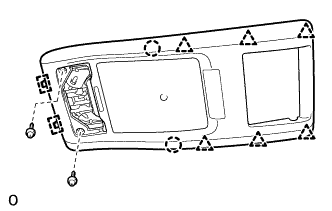
w/o Sliding Roof:
-
Remove the 2 screws.
-
Detach the 6 clips, 2 claws and 2 hooks and remove the roof console box assembly.
-
Disconnect the connector.
-
-
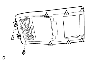
w/ Sliding Roof:
-
Remove the 2 screws.
-
Detach the 6 clips and 2 hooks and remove the roof console box assembly.
-
Disconnect the connector.
-
-
-
REMOVE SPOT LIGHT ASSEMBLY
-
Using moulding remover D, detach the 4 claws and remove the spot light assembly.
-
Disconnect the connector.
-
-
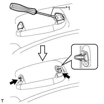
REMOVE REAR VANITY LIGHT ASSEMBLY
Tech Tips
Use the same procedure to remove the vanity light on the other side.
-
Using a screwdriver, detach the 4 claws and remove the lens.
Tech Tips
Tape the screwdriver tip before use.
-
Remove the 2 screws.
-
Using moulding remover D, detach the claw and remove the vanity light assembly.
-
Disconnect the connector.
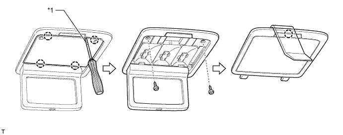
Text in Illustration *1 Protective Tape - -
-
-
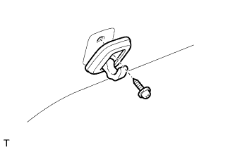
REMOVE COAT HOOK
Tech Tips
Use the same procedure to remove the hook on the other side.
-
Remove the screw and coat hook.
-
-
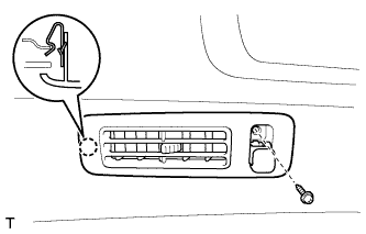
REMOVE ROOF SIDE REGISTER BEZEL LH (w/ Rear Cooler)
-
Remove the screw.
-
Detach the claw and remove the roof side register LH.
-
-
REMOVE ROOF SIDE REGISTER BEZEL RH (w/ Rear Cooler)
Tech Tips
Use the same procedure described for the LH side.
-
REMOVE ASSIST GRIP SUB-ASSEMBLY
Text in Illustration *1 Protective Tape Tech Tips
Use the same procedure for all the assist grips.
-
Using a screwdriver, detach the 4 claws and remove the 2 assist grip covers.
Tech Tips
Tape the screwdriver tip before use.
-
Detach the 2 clips and remove the assist grip sub-assembly.
-
-
REMOVE ROOF HEADLINING ASSEMBLY
-
for Standard Body:
Tech Tips
It is not necessary to completely remove the roof headlining. Slightly lower the rear section of the roof headlining Click here so that the back window glass can be removed in a later step.
-
for Long Body:
Tech Tips
It is not necessary to completely remove the roof headlining. Slightly lower the rear section of the roof headlining Click here so that the back window glass can be removed in a later step.
-
-
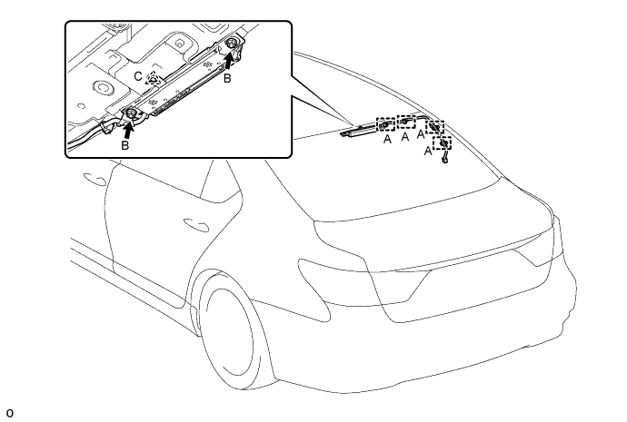
REMOVE AMPLIFIER ANTENNA ASSEMBLY
-
Disconnect each connector.
-
Detach the 4 clamps labeled A and remove the 2 nuts labeled B.
-
Detach the clip labeled C and remove the amplifier antenna.
Tech Tips
-
Remove the clip if it is damaged.
-
The clip is used when the vehicle is assembled at the factory and is not needed for the reinstallation.
-
-
-
REMOVE FRONT FENDER TO COWL SIDE SEAL LH
-

Detach the clip and claw, and then remove the cowl side seal LH.
-
-
REMOVE FRONT FENDER TO COWL SIDE SEAL RH
Tech Tips
Use the same procedures described for the No. 2 clip.
-
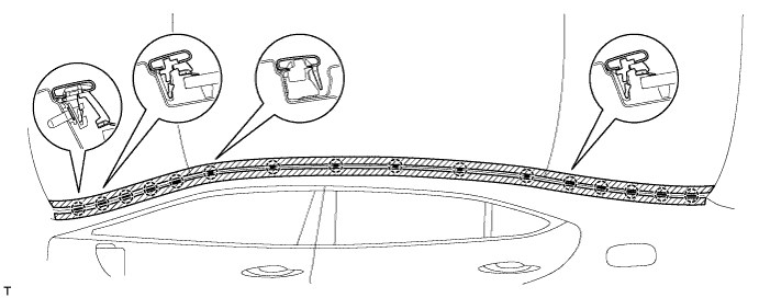
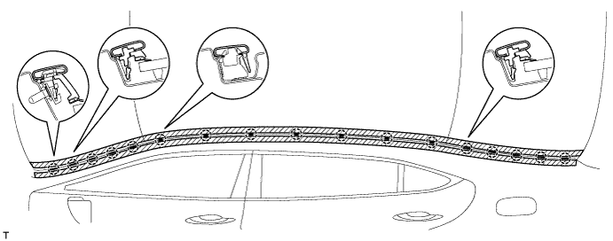
REMOVE ROOF DRIP SIDE FINISH MOULDING CENTER LH
-
Put protective tape around the moulding.
-
for Standard Body:
Using a moulding remover, detach the 16 clips and remove the moulding.
-
for Long Body:
Using a moulding remover, detach the 17 clips and remove the moulding.
Note
-
Do not remove the clips from the vehicle body.
-
If the clips are damaged or removed accidentally, replace them.
-
-
-
REMOVE ROOF DRIP SIDE FINISH MOULDING CENTER RH
Tech Tips
Use the same procedures described for the LH side.
-
REMOVE NO. 2 WINDSHIELD OUTSIDE MOULDING CLIP

Tech Tips
Perform the following procedure if replacing the No. 2 moulding clip.
-
Remove the No. 2 moulding clip.
-
-
REMOVE NO. 1 WINDSHIELD OUTSIDE MOULDING CLIP
Tech Tips
Use the same procedures described for the No. 2 windshield outside moulding clip.
-
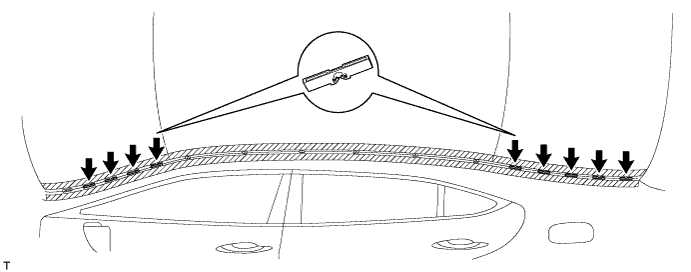
REMOVE ROOF NO. 2 DRIP SIDE FINISH MOULDING CLIP
Tech Tips
Perform the following procedure if replacing the No. 2 moulding clips.
-
Remove the 9 No. 2 moulding clips.
-
-
REMOVE NO. 3 WINDSHIELD OUTSIDE MOULDING CLIP
Tech Tips
Perform the following procedure if replacing the No. 3 windshield outside moulding clip.
-
Put a 4 mm (0.16 in.) drill bit into a drill.
-
Wind tape around the drill bit approximately 5 mm (0.20 in.) from the tip of the drill.
Tech Tips
Tape the 4 mm (0.16 in.) drill bit to prevent the drill bit from going too deep.
-
Lightly press the drill against the rivets, drill off the flanges of the rivets, and remove the 10 rivets.
Note
-
Pressing the drill too firmly will cause the rivet to turn and result in the rivet not being drilled through.
-
Do not pry the rivets with the drill, because this may cause damage to the installation holes of the rivets or the drill bit.
-
Be careful of the drilled rivets as they may become hot.
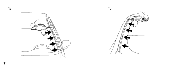
Text in Illustration *a Front Side *b Rear Side -
-
Using a vacuum cleaner, remove the rivet fragments and shavings from the drilled areas.
-
-
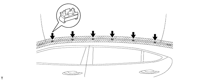
REMOVE ROOF NO. 1 DRIP SIDE FINISH MOULDING CLIP
Tech Tips
Perform the following procedure if replacing the No. 1 roof drip side finish moulding clips.
-
for Standard Body:
Remove the 6 No. 1 roof drip side finish moulding clips.
-
for Long Body:
Remove the 7 No. 1 roof drip side finish moulding clips.

-
-
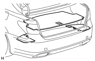
REMOVE LUGGAGE COMPARTMENT MAT SUB-ASSEMBLY
-
REMOVE ROPE HOOK ASSEMBLY
-
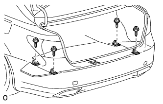
Remove the 4 bolts and 4 rope hook assemblies.
-
-
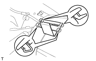
REMOVE ROPE HOOK
-
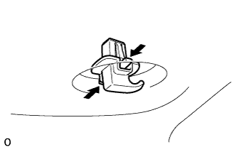
Remove the 4 rope hooks by pushing the claws in the direction of the arrows in the illustration.
-
-
REMOVE DECK TRIM SIDE BOARD LH
-
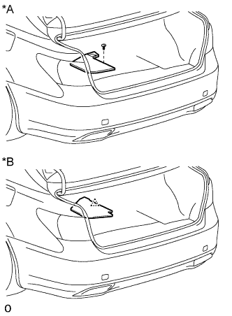
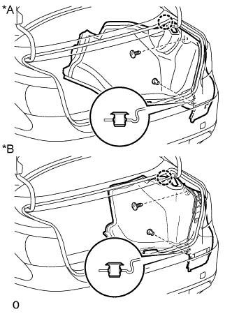
Text in Illustration *A w/ Spare Tire *B w/o Spare Tire w/ Spear Tire:
-
Remove the clip.
-
Remove the deck trim side board LH.
-
-
w/o Spear Tire:
-
Detach the clip and deck trim side board LH.
-
-
-
REMOVE DECK TRIM SIDE BOARD RH
-
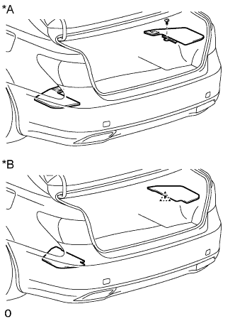
Text in Illustration *A w/ Spare Tire *B w/o Spare Tire w/ Spear Tire:
-
Remove the clip.
-
Remove the deck trim side board RH.
-
-
w/o Spear Tire:
-
Detach the clip and deck trim side board RH.
-
-
-
REMOVE LUGGAGE COMPARTMENT NO. 1 LIGHT ASSEMBLY
-

Text in Illustration *1 Protective Tape Using a screwdriver, detach the 2 claws and remove the No. 1 luggage compartment light assembly.
Tech Tips
Tape the screwdriver tip before use.
-
-
REMOVE LUGGAGE COMPARTMENT NO. 2 TRIM HOOK (w/ Rear Cooler)
-
Detach the No. 2 luggage compartment trim hook.
-
-
REMOVE FRONT LUGGAGE COMPARTMENT TRIM COVER
-
w/o Rear Cooler:
-
Remove the 4 claws, 3 clips and front luggage compartment trim cover.
-
-
w/ Rear Cooler:
-
Remove the 4 claws, 5 clips and front luggage compartment trim cover.
-
-
-
REMOVE REAR FLOOR FINISH PLATE
-
Remove the 3 clips.
-
Detach the 4 clips and remove the rear floor finish plate.
-
-
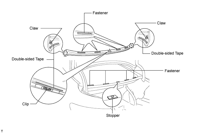
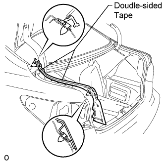
REMOVE BACK WINDOW MOULDING OUTSIDE LOWER
-
Using a screwdriver, detach the 2 claws, 4 fasteners and double-sided tape (3 areas). Slide the moulding toward the front of the vehicle along the back window glass to detach the clip. Then remove the moulding.
Note
-
Be careful not to damage the vehicle body.
-
Do not lift the moulding or slide it toward the rear of the vehicle when detaching the clip.
-
The moulding is a non-reusable part.
Tech Tips
Tape the screwdriver tip before use.
-
-
-
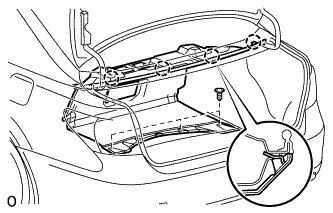
REMOVE LUGGAGE COMPARTMENT TRIM COVER ASSEMBLY LH
-

Text in Illustration *A w/o Rear Cooler *B w/ Rear Cooler Remove the 2 clips.
-
Detach the claw and luggage compartment trim cover assembly LH.
-
-
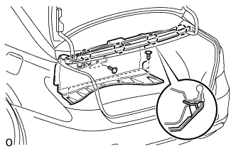
REMOVE LUGGAGE COMPARTMENT TRIM COVER ASSEMBLY RH
-
Text in Illustration *A w/o Rear Cooler *B w/ Rear Cooler Remove the 2 clips.
-
Detach the claw and luggage compartment trim cover assembly RH.
-
-
REMOVE REAR COMBINATION LIGHT ASSEMBLY LH
-
Put protective tape around the rear combination light assembly LH.
-
Disconnect the connector.
-
Remove the 3 nuts.
-
Move the rear combination light assembly LH in the direction of the arrow in the illustration, detach the clip, 2 claws and 2 guides to remove the rear combination light assembly LH.
Tech Tips
The clips remain on the vehicle body.
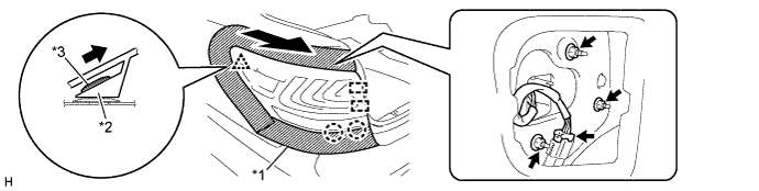
Text in Illustration *1 Protective Tape *2 Rear Combination Light Assembly LH *3 Clip - -
-
-
REMOVE REAR COMBINATION LIGHT ASSEMBLY RH
Tech Tips
Use the same procedure described for the LH side.
-
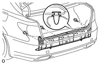
REMOVE LUGGAGE COMPARTMENT DOOR HINGE COVER LH
-
Using a screwdriver, detach the double-sided tape (2 areas) and 2 clips. Then remove the hinge cover.
Note
-
Be careful not to damage the vehicle body.
-
The hinge cover is a non-reusable part.
Tech Tips
Tape the screwdriver tip before use.
-
-
-
REMOVE LUGGAGE COMPARTMENT DOOR HINGE COVER RH
Tech Tips
Use the same procedures described for the LH side.
-
REMOVE NO. 2 CENTER STOP LIGHT COVER
-
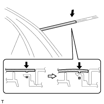
Push in the No. 2 center stop light cover at a point 10 mm (0.393 in.) from the end of the cover as shown in the illustration.
-
With the No. 2 center stop light cover pushed in, slide it towards the outside of the vehicle to detach the 4 claws.
-
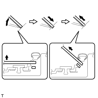
Lift up the No. 2 center stop light cover to remove it as shown in the illustration.
-
-
REMOVE CENTER STOP LIGHT COVER
-
Push in the center stop light cover at a point 10 mm (0.393 in.) from the end of the cover as shown in the illustration.
-
With the center stop light cover pushed in, slide it towards the outside of the vehicle to detach the 4 claws.
-
Lift up the center stop light cover to remove it as shown in the illustration.
-
-
REMOVE CENTER STOP LIGHT CLIP
-
Turn the 2 center stop light clips 90° and remove them.
-
-
REMOVE CENTER STOP LIGHT ASSEMBLY
-
Disconnect the harness and connector.
-
Remove the 2 screws.
-
Detach the 2 claws and remove the center stop light assembly.
-
-
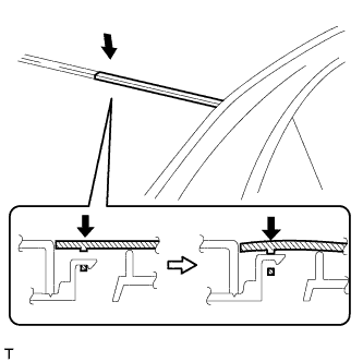
REMOVE BACK WINDOW GLASS
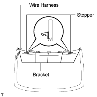
Note
As the stopper, bracket and harness are not supplied individually, be careful not to damage them when installing the back window glass.
-
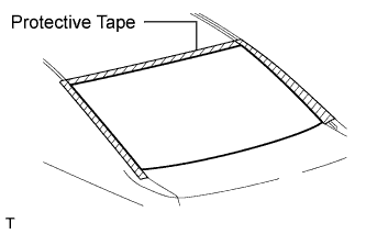
Apply protective tape to the outer surface of the vehicle body to prevent scratches.
Note
When separating the back window glass from the vehicle, be careful not to damage the vehicle's paint or interior/exterior ornaments.
-
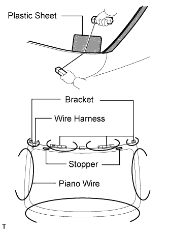
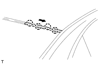
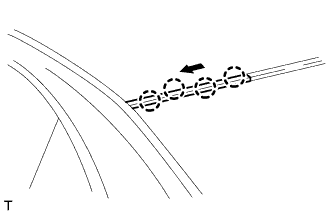
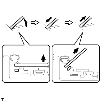
From the interior, insert a piano wire between the vehicle body and back window glass as shown in the illustration.
Note
-
If the stopper is damaged, the back window glass assembly must be replaced. Be careful when performing the procedure.
-
Make sure not to deform the upper brackets.
-
Make sure not to damage the wire harness.
-
-
Tie objects that can serve as handles (for example, wooden blocks) to both wire ends.
-
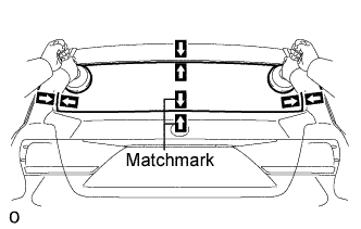
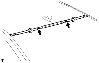
Place matchmarks over the glass and vehicle body on the locations indicated in the illustration.
Tech Tips
Matchmarks do not need to be placed if the glass is not going to be reused.
-
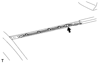
Cut through the adhesive by pulling the piano wire around the back window glass.
Note
Leave as much adhesive on the vehicle body as possible when removing the back window glass.
-
Using suction cups, remove the back window glass.
Note
If the stopper is damaged, the back window glass assembly must be replaced. Be careful when performing the procedure.
-
-
CLEAN BACK WINDOW GLASS
-
Clean the outer edge of the back window glass with a non-residue solvent.
Note
-
Do not touch the back window glass surface after cleaning it.
-
Be careful not to damage the glass.
-
Even if using new back window glass, clean the back window glass with a non-residue solvent.
-
-
-
CLEAN VEHICLE BODY
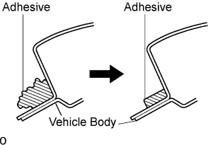
-
Using a scraper, remove the moulding and adhesive from the back window glass.
-
Clean and shape the contact surface of the vehicle body.
-
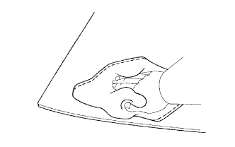
On the contact surface of the vehicle body, use a knife to cut away excess adhesive as shown in the illustration.
Tech Tips
Leave as much adhesive on the vehicle body as possible.
Note
Be careful not to damage the vehicle body.
-
Clean the contact surface of the vehicle body with cleaner.
Tech Tips
Even if all the adhesive has been removed, clean the vehicle body.
-
-