CLEARANCE WARNING ECU REMOVAL

-
PRECAUTION
CAUTION:
After turning the engine switch off, waiting time may be required before disconnecting the cable from the battery terminal. Therefore, make sure to read the disconnecting the cable from the battery terminal notice before proceeding with work Click here.
-
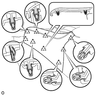
REMOVE COWL TOP VENTILATOR LOUVER RH

-
Remove the 6 clips and cowl top ventilator louver RH.
-
-
DISCONNECT CABLE FROM NEGATIVE BATTERY TERMINAL
CAUTION:
Wait at least 90 seconds after disconnecting the cable from the negative (-) battery terminal to disable the SRS system.
Note
When disconnecting the cable, some systems need to be initialized after the cable is reconnected Click here.
-
REMOVE INSTRUMENT PANEL FINISH PANEL END RH (for LHD)
Tech Tips
Use the same procedure described for the LH side.
-
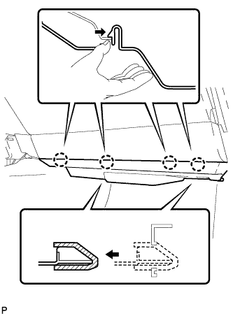
REMOVE INSTRUMENT PANEL FINISH PANEL END LH (for RHD)
-
Pull the front part of the instrument panel finish panel end LH to detach the 6 clips.
-
Pull the instrument panel finish panel end LH to detach 3 clips and remove the instrument panel finish panel end LH.
-
-
REMOVE INSTRUMENT SIDE PANEL RH (for LHD)
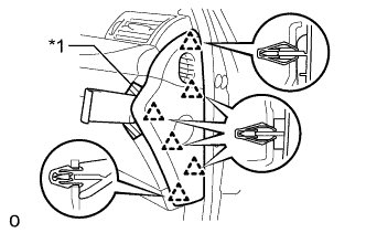
Text in Illustration *1 Protective Tape
-
Apply protective tape as shown in the illustration.
-
Using moulding remover D, detach the 6 clips and remove the instrument side panel RH.
-
-
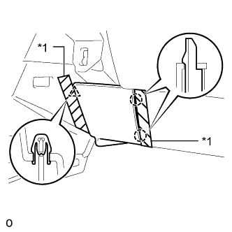
REMOVE INSTRUMENT SIDE PANEL LH (for RHD)
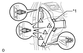
Text in Illustration *1 Protective Tape
-
Apply protective tape as shown in the illustration.
-
Using moulding remover D, detach the 6 clips and remove the instrument side panel LH.
-
-
REMOVE NO. 2 INSTRUMENT PANEL UNDER COVER SUB-ASSEMBLY
-
Detach the 4 claws and remove the No. 2 instrument panel under cover sub-assembly.
-
Disconnect the connector.
-
-
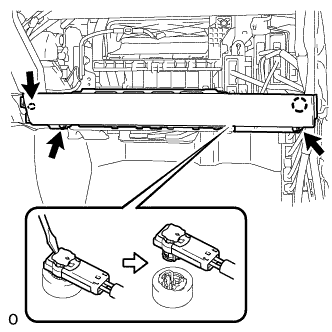
REMOVE LOWER INSTRUMENT PANEL
-
Text in Illustration *1 Protective Tape Put protective tape around the lower instrument panel.
-
Using a screwdriver, detach the clip and 2 claws to remove the lower instrument panel.
-
-
REMOVE FRONT PASSENGER SIDE KNEE AIRBAG ASSEMBLY
-
Check that the engine switch is off.
-
Check that the cable is disconnected from the negative (-) battery terminal.
CAUTION:
Wait at least 90 seconds after disconnecting the cable from the negative (-) battery terminal to disable the SRS system.
-
Remove the 3 bolts.
-
Detach the claw to remove the front passenger side knee airbag assembly.
-
Using a screwdriver release the airbag connector lock.
-
Using a screwdriver, disconnect the airbag connector.
Note
When disconnecting airbag connector, take care not to damage the airbag wire harness.
-
-
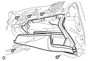
REMOVE GLOVE COMPARTMENT DOOR ASSEMBLY
-
Remove the 5 screws <C> and glove compartment door assembly.
-
Disconnect each connector and each wire harness clamp.
-
-
REMOVE CLEARANCE WARNING ECU ASSEMBLY
-
for LHD:
-
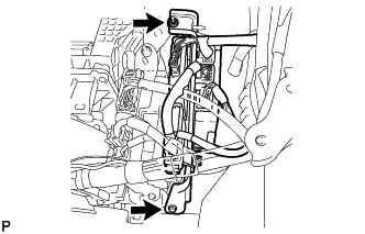
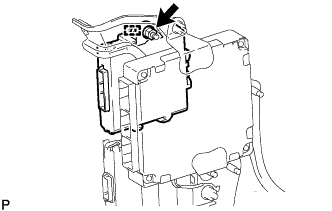
Remove the bolt and nut.
-
Disconnect each connector and remove the ECU integration bracket.
Note
Do not forcibly disconnect the connector.
-
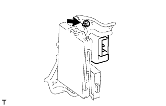
Remove the nut.
-
Detach the guide and remove the clearance warning ECU assembly.
Note
-
Avoid any impact to the clearance warning ECU.
-
Do not drop the ECU. If it is dropped, replace it with a new one.
-
-
-
for RHD:
-
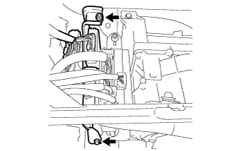
Remove the bolt and nut.
-
Disconnect each connector and remove the ECU integration bracket.
Note
Do not forcibly disconnect the connector.
-
Remove the nut and clearance warning ECU assembly.
Note
-
Avoid any impact to the clearance warning ECU.
-
Do not drop the ECU. If it is dropped, replace it with a new one.
-
-
-