RADIO ANTENNA CORD INSTALLATION

Tech Tips
-
Use the same procedure for RHD and LHD vehicles.
-
The procedure listed below is for LHD vehicles.
-
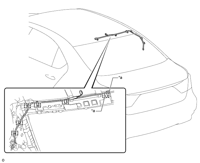
INSTALL NO. 3 ANTENNA CORD SUB-ASSEMBLY
-
Attach the 6 clamps and install the No. 3 antenna cord sub-assembly.
-
Connect each connector.
Text in Illustration *a w/ Digital Audio Broadcasting - -
-
-
INSTALL ROOF HEADLINING ASSEMBLY
-
for Standard Body:
-
for Long Body:
-
-
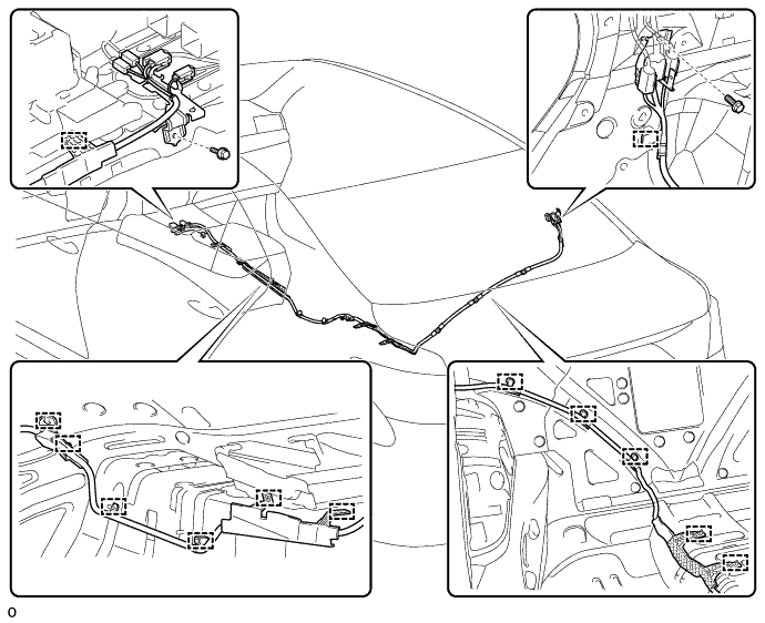
INSTALL NO. 2 ANTENNA CORD SUB-ASSEMBLY
-
for Long Body:
-
Attach the 13 clamps.
-
Install the 2 bolts.
- Torque:
- 8.4 N*m { 86 kgf*cm, 74 in.*lbf }
-
Connect each connector and install the No. 2 antenna cord sub-assembly.
-
-
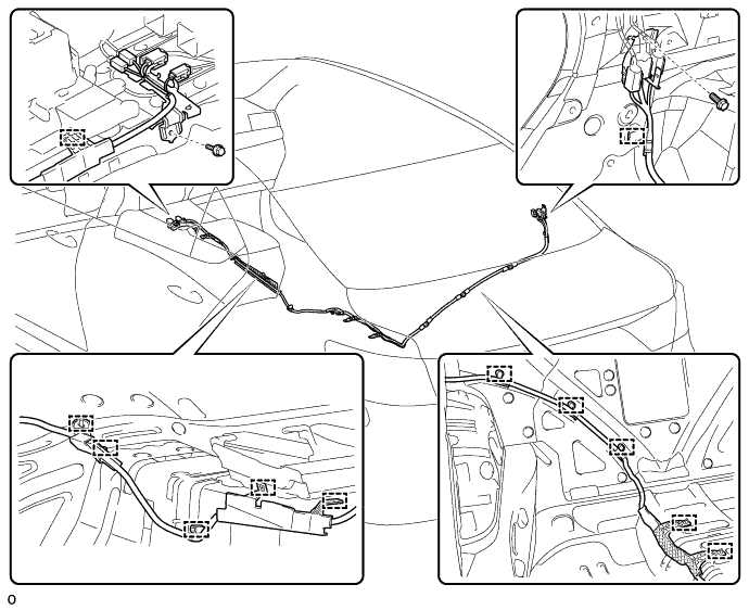
for Standard Body:
-
Attach the 12 clamps.
-
Install the 2 bolts.
- Torque:
- 8.4 N*m { 86 kgf*cm, 74 in.*lbf }
-
Connect each connector and install the No. 2 antenna cord sub-assembly.
-
-
-
INSTALL ROOF SIDE GARNISH INNER RH
-
INSTALL REAR SEAT ASSEMBLY
-
for Power Seat:
-
for 4-Passenger with Ottoman:
-
for 5-Passenger with Ottoman:
-
for Fixed Seat:
-
-
INSTALL FRONT SEAT ASSEMBLY RH
-
INSTALL FRONT CONSOLE BOX ASSEMBLY
-
w/o Rear Entertainment System:
-
for 5-Passenger with Ottoman:
-
w/ Disc Player:
-
-
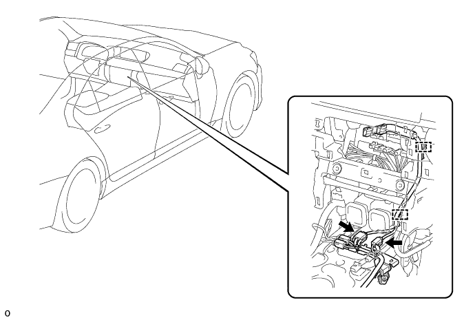
INSTALL ANTENNA CORD SUB-ASSEMBLY
-
Attach the 2 clamps to install the antenna cord sub-assembly.
-
Connect each connector.
-
-
INSTALL MULTI-MEDIA MODULE RECEIVER ASSEMBLY
-
Connect the connectors.
-
Insert the multi-media module receiver assembly with bracket.
Note
When inserting the radio receiver, do not press the knobs on it.
-
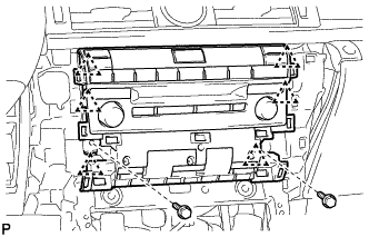
Attach the 6 clips.
-
Install the multi-media module receiver assembly with bracket with the 2 bolts.
-
-
INSTALL LOWER NO. 1 INSTRUMENT PANEL FINISH PANEL
-
Connect the connector.
-
Attach the 5 guides and 4 clips to install the lower No. 1 instrument panel finish panel.
-
-
INSTALL LOWER NO. 2 INSTRUMENT PANEL FINISH PANEL
-
Attach the 5 guides and 4 clips to install the lower No. 2 instrument panel finish panel.
-
-
INSTALL UPPER CONSOLE PANEL SUB-ASSEMBLY
-
Attach the 6 clips to install the upper console panel sub-assembly.
-
Connect the connector.
-
-
INSTALL UPPER INSTRUMENT CLUSTER FINISH PANEL
-
Attach the 5 clips to install the upper instrument cluster finish panel.
-
-
INSTALL UPPER REAR CONSOLE PANEL SUB-ASSEMBLY
-
Connect each connector and attach each wire harness clamp.
-
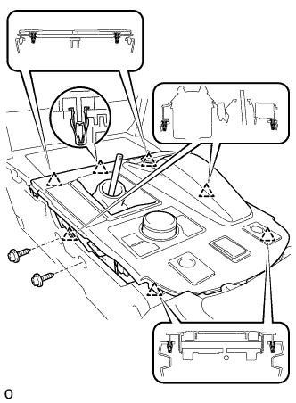
Attach the 6 clips to install the upper rear console panel sub-assembly.
-
Install the 2 screws.
-
-
INSTALL NO. 3 BOX PANEL
-
Attach the 4 claws to install the No. 3 box panel.
-
-
INSTALL SHIFT LEVER KNOB SUB-ASSEMBLY
-
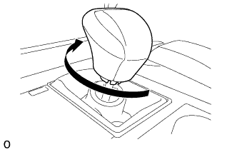
Twist the shift lever knob sub-assembly in the direction indicated by the arrow to install it.
-
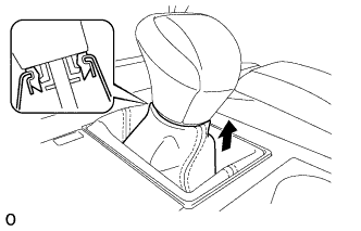
Pull up the shift lever boot to connect it to the shift lever knob sub-assembly.
-
-
INSTALL INSTRUMENT PANEL FINISH PANEL END RH
Tech Tips
Use the same procedure described for the LH side.
-
INSTALL INSTRUMENT PANEL FINISH PANEL END LH
-
Attach the rear part of the instrument panel finish panel end LH 3 clips.
-
Attach the front part of the instrument panel finish panel end LH 6 clips to install the instrument panel finish panel end LH.
-
-
CONNECT CABLE TO NEGATIVE BATTERY TERMINAL
Note
When disconnecting the cable, some systems need to be initialized after the cable is reconnected Click here.
-
INSTALL COWL TOP VENTILATOR LOUVER RH
-

Install the 6 clips and cowl top ventilator louver RH.
Note
If the cowl top ventilator louver RH is not properly installed, water may leak into the engine room and cause malfunctions. Therefore, make sure the cowl top ventilator louver RH is installed properly.
-