CAN COMMUNICATION SYSTEM (for RHD) Open in One Side of CAN Branch Line
DESCRIPTION
If 2 or more ECUs and/or sensors do not appear on the intelligent tester "Bus Check" screen, one side of the CAN branch wire may be open (one side of the CANH [CAN branch wire]/CANL [CAN branch wire] of the ECU and/or sensor is open).
| Symptom | Trouble Area |
| 2 or more ECUs and/or sensors do not appear on the intelligent tester "Bus Check" screen. |
|
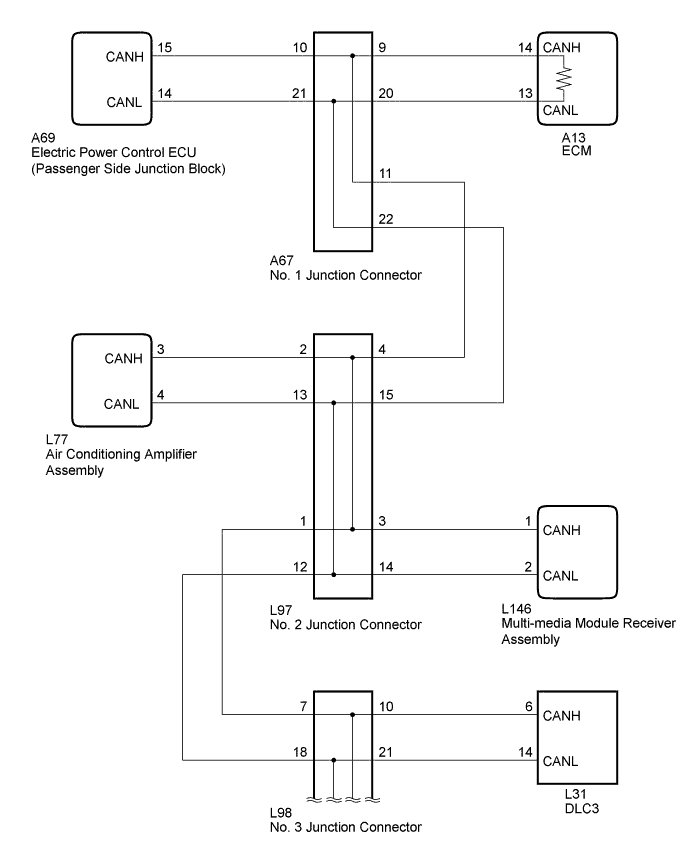
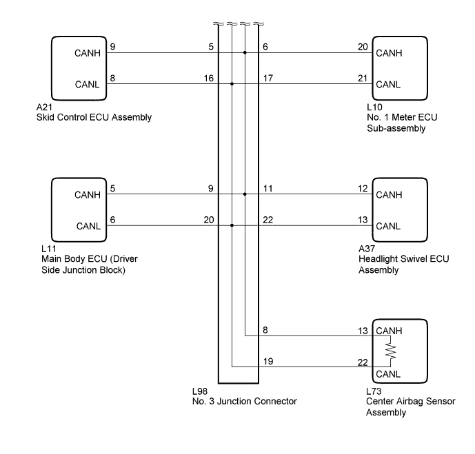
WIRING DIAGRAM
INSPECTION PROCEDURE
Note
-
The vehicle is equipped with an SRS (Supplemental Restraint System) which includes components such as airbags. Before servicing (including removal or installation of parts), be sure to read the Precaution in the SRS Click here.
-
After turning the engine switch off, waiting time may be required before disconnecting the cable from the battery terminal. Therefore, make sure to read the disconnecting the cable from the battery terminal notice before proceeding with work Click here.
Tech Tips
-
Perform the following inspection for the ECUs (sensors) which are displayed on the intelligent tester. If a malfunction cannot be identified, perform the following inspections for the ECUs (sensors) connected to the CAN communication system.
-
Do not remove the ECM or center airbag sensor assembly as they are the end parts of the circuit. If removed, CAN communication will not be possible.
-
The open circuit confirmation of the ECM, center airbag sensor assembly and CAN main wire is performed in the CAN V bus line check procedure of "How to Proceed with Troubleshooting". This inspection only has procedures for checking for an open circuit on one side of a CAN branch wire.
PROCEDURE
-
CHECK FOR OPEN IN ONE SIDE OF CAN BRANCH WIRE (ELECTRIC POWER CONTROL ECU)
-
Disconnect the A69 electric power control ECU (passenger side junction block) connector.
-
Select "Bus Check" on the intelligent tester Click here.
Result Result Proceed to "Electric Power Control" is not displayed on the intelligent tester A "Electric Power Control" is not displayed on the intelligent tester B
B 
CHECK FOR OPEN IN ONE SIDE OF CAN BRANCH WIRE (NO. 1 METER ECU SUB-ASSEMBLY) Click here
A 
-
-
CHECK FOR OPEN IN ONE SIDE OF CAN BRANCH WIRE (ELECTRIC POWER CONTROL ECU CAN BRANCH WIRE)
-
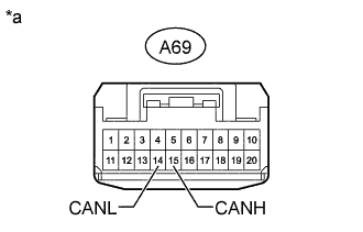
Text in Illustration *a Front view of wire harness connector
(to Electric Power Control ECU [Passenger Side Junction Block])
Disconnect the cable from the negative (-) battery terminal before measuring the resistances of the CAN main wire and the CAN branch wire.
CAUTION:
Wait at least 90 seconds after disconnecting the cable from the negative (-) battery terminal to disable the SRS system.
Note
When disconnecting the cable, some systems need to be initialized after the cable is reconnected Click here.
-
Measure the resistance according to the value(s) in the table below.
Standard Resistance Tester Connection Switch Condition Specified Condition A69-15 (CANH) - A69-14 (CANL) Engine switch off 54 to 69 Ω
NG 
REPAIR OR REPLACE CAN BRANCH WIRE OR CONNECTOR (ELECTRIC POWER CONTROL ECU)
OK 
REPLACE ELECTRIC POWER CONTROL ECU (PASSENGER SIDE JUNCTION BLOCK)
-
-
CHECK FOR OPEN IN ONE SIDE OF CAN BRANCH WIRE (AIR CONDITIONING AMPLIFIER ASSEMBLY)
-
Disconnect the L77 air conditioning amplifier assembly connector.
-
Select "Bus Check" on the intelligent tester Click here.
Result Result Proceed to "Air Conditioning Amplifier" is not displayed on the intelligent tester A "Air Conditioning Amplifier" is not displayed on the intelligent tester B
B
CHECK FOR OPEN IN ONE SIDE OF CAN BRANCH WIRE (HEADLIGHT SWIVEL ECU ASSEMBLY CAN BRANCH WIRE) Click here
A
-
-
CHECK FOR OPEN IN ONE SIDE OF CAN BRANCH WIRE (AIR CONDITIONING AMPLIFIER ASSEMBLY CAN BRANCH WIRE)
-
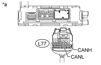
Text in Illustration *a Rear view of wire harness connector
(to Air Conditioning Amplifier Assembly)
Disconnect the cable from the negative (-) battery terminal before measuring the resistances of the CAN main wire and the CAN branch wire.
CAUTION:
Wait at least 90 seconds after disconnecting the cable from the negative (-) battery terminal to disable the SRS system.
Note
When disconnecting the cable, some systems need to be initialized after the cable is reconnected Click here.
-
Measure the resistance according to the value(s) in the table below.
Standard Resistance Tester Connection Switch Condition Specified Condition L77-3 (CANH) - L77-4 (CANL) Engine switch off 54 to 69 Ω
NG
REPAIR OR REPLACE CAN BRANCH WIRE OR CONNECTOR (AIR CONDITIONING AMPLIFIER ASSEMBLY)
OK
REPLACE AIR CONDITIONING AMPLIFIER ASSEMBLY Click here
-
-
CHECK FOR OPEN IN ONE SIDE OF CAN BRANCH WIRE (MULTI-MEDIA MODULE RECEIVER ASSEMBLY)
-
Disconnect the L146 multi-media module receiver assembly connector.
-
Select "Bus Check" on the intelligent tester Click here.
Result Result Proceed to "Display and Navigation (AVN1)" is not displayed on the intelligent tester A "Display and Navigation (AVN1)" is not displayed on the intelligent tester B
B
CHECK FOR OPEN IN ONE SIDE OF CAN BRANCH WIRE (MAIN BODY ECU) Click here
A
-
-
CHECK FOR OPEN IN ONE SIDE OF CAN BRANCH WIRE (MULTI-MEDIA MODULE RECEIVER ASSEMBLY CAN BRANCH WIRE)
-
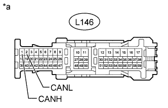
Text in Illustration *a Front view of wire harness connector
(to Multi-media Module Receiver Assembly)
Disconnect the cable from the negative (-) battery terminal before measuring the resistances of the CAN main wire and the CAN branch wire.
CAUTION:
Wait at least 90 seconds after disconnecting the cable from the negative (-) battery terminal to disable the SRS system.
Note
When disconnecting the cable, some systems need to be initialized after the cable is reconnected Click here.
-
Measure the resistance according to the value(s) in the table below.
Standard Resistance Tester Connection Switch Condition Specified Condition L146-1 (CANH) - L146-2 (CANL) Engine switch off 54 to 69 Ω
NG
REPAIR OR REPLACE CAN BRANCH WIRE OR CONNECTOR (MULTI-MEDIA MODULE RECEIVER ASSEMBLY)
OK
REPLACE MULTI-MEDIA MODULE RECEIVER ASSEMBLY Click here
-
-
CHECK FOR OPEN IN ONE SIDE OF CAN BRANCH WIRE (SKID CONTROL ECU ASSEMBLY)
-
Disconnect the A21 skid control ECU assembly connector.
-
Select "Bus Check" on the intelligent tester Click here.
Result Result Proceed to "Skid Control (ABS/VSC/TRAC)" is not displayed on the intelligent tester A "Skid Control (ABS/VSC/TRAC)" is not displayed on the intelligent tester B
B
CHECK FOR OPEN IN ONE SIDE OF CAN BRANCH WIRE (AIR CONDITIONING AMPLIFIER ASSEMBLY) Click here
A
-
-
CHECK FOR OPEN IN ONE SIDE OF CAN BRANCH WIRE (SKID CONTROL ECU ASSEMBLY CAN BRANCH WIRE)
-
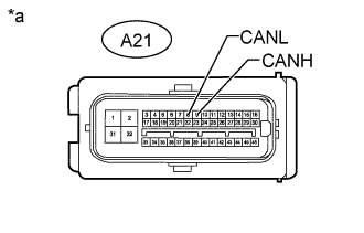
Text in Illustration *a Front view of wire harness connector
(to Skid Control ECU Assembly)
Disconnect the cable from the negative (-) battery terminal before measuring the resistances of the CAN main wire and the CAN branch wire.
CAUTION:
Wait at least 90 seconds after disconnecting the cable from the negative (-) battery terminal to disable the SRS system.
Note
When disconnecting the cable, some systems need to be initialized after the cable is reconnected Click here.
-
Measure the resistance according to the value(s) in the table below.
Standard Resistance Tester Connection Switch Condition Specified Condition A21-9 (CANH) - A21-8 (CANL) Engine switch off 54 to 69 Ω
NG
REPAIR OR REPLACE CAN BRANCH WIRE OR CONNECTOR (SKID CONTROL ECU ASSEMBLY)
OK
REPLACE SKID CONTROL ECU ASSEMBLY Click here
-
-
CHECK FOR OPEN IN ONE SIDE OF CAN BRANCH WIRE (NO. 1 METER ECU SUB-ASSEMBLY)
-
Disconnect the L10 No. 1 meter ECU sub-assembly connector.
-
Select "Bus Check" on the intelligent tester Click here.
Result Result Proceed to "Combination Meter" is not displayed on the intelligent tester A "Combination Meter" is not displayed on the intelligent tester B
B
CHECK FOR OPEN IN ONE SIDE OF CAN BRANCH WIRE (SKID CONTROL ECU ASSEMBLY) Click here
A
-
-
CHECK FOR OPEN IN ONE SIDE OF CAN BRANCH WIRE (NO. 1 METER ECU SUB-ASSEMBLY CAN BRANCH WIRE)
-
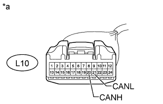
Text in Illustration *a Front view of wire harness connector
(to No. 1 Meter ECU Sub-assembly)
Disconnect the cable from the negative (-) battery terminal before measuring the resistances of the CAN main wire and the CAN branch wire.
CAUTION:
Wait at least 90 seconds after disconnecting the cable from the negative (-) battery terminal to disable the SRS system.
Note
When disconnecting the cable, some systems need to be initialized after the cable is reconnected Click here.
-
Measure the resistance according to the value(s) in the table below.
Standard Resistance Tester Connection Switch Condition Specified Condition L10-20 (CANH) - L10-21 (CANL) Engine switch off 54 to 69 Ω
NG
REPAIR OR REPLACE CAN BRANCH WIRE OR CONNECTOR (NO. 1 METER ECU SUB-ASSEMBLY)
OK
REPLACE NO. 1 METER ECU SUB-ASSEMBLY Click here
-
-
CHECK FOR OPEN IN ONE SIDE OF CAN BRANCH WIRE (MAIN BODY ECU)
-
Disconnect the L11 main body ECU (driver side junction block) connector.
-
Select "Bus Check" on the intelligent tester Click here.
Result Result Proceed to "Main Body" is not displayed on the intelligent tester A "Main Body" is not displayed on the intelligent tester B
B
CHECK FOR OPEN IN ONE SIDE OF CAN BRANCH WIRE (MULTI-MEDIA MODULE RECEIVER ASSEMBLY) Click here
A
-
-
CHECK FOR OPEN IN ONE SIDE OF CAN BRANCH WIRE (MAIN BODY ECU CAN BRANCH WIRE)
-
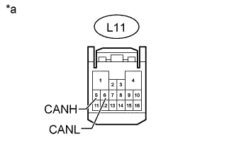
Text in Illustration *a Front view of wire harness connector
(to Main Body ECU [Driver Side Junction Block])
Disconnect the cable from the negative (-) battery terminal before measuring the resistances of the CAN main wire and the CAN branch wire.
CAUTION:
Wait at least 90 seconds after disconnecting the cable from the negative (-) battery terminal to disable the SRS system.
Note
When disconnecting the cable, some systems need to be initialized after the cable is reconnected Click here.
-
Measure the resistance according to the value(s) in the table below.
Standard Resistance Tester Connection Switch Condition Specified Condition L11-5 (CANH) - L11-6 (CANL) Engine switch off 54 to 69 Ω
NG
REPAIR OR REPLACE CAN BRANCH WIRE OR CONNECTOR (MAIN BODY ECU)
OK
REPLACE MAIN BODY ECU (DRIVER SIDE JUNCTION BLOCK)
-
-
CHECK FOR OPEN IN ONE SIDE OF CAN BRANCH WIRE (HEADLIGHT SWIVEL ECU ASSEMBLY CAN BRANCH WIRE)
-
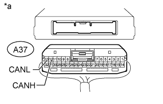
Text in Illustration *a Rear view of wire harness connector
(to Headlight Swivel ECU Assembly)
Disconnect the cable from the negative (-) battery terminal before measuring the resistances of the CAN main wire and the CAN branch wire.
CAUTION:
Wait at least 90 seconds after disconnecting the cable from the negative (-) battery terminal to disable the SRS system.
Note
When disconnecting the cable, some systems need to be initialized after the cable is reconnected Click here.
-
Disconnect the headlight swivel ECU assembly connector.
-
Measure the resistance according to the value(s) in the table below.
Standard Resistance Tester Connection Switch Condition Specified Condition A37-12 (CANH) - A37-13 (CANL) Engine switch off 54 to 69 Ω
NG
REPAIR OR REPLACE CAN BRANCH WIRE OR CONNECTOR (HEADLIGHT SWIVEL ECU ASSEMBLY)
OK
REPLACE HEADLIGHT SWIVEL ECU ASSEMBLY Click here
-