COMPRESSOR (for 2WD) INSTALLATION

-
ADJUST COMPRESSOR OIL
-
When replacing the compressor and magnetic clutch with a new one, gradually discharge the refrigerant gas from the service valve, and drain the following amount of oil from the new compressor and magnetic clutch before installation.
Standard (Except G.C.C) (Oil capacity inside the new compressor and magnetic clutch: 130 + 15 cc (4.6 + 0.51 fl. oz.) ) - (Remaining oil amount in the removed compressor and magnetic clutch) = (Oil amount to be removed from the new compressor when replacing) Standard (G.C.C) (Oil capacity inside the new compressor and magnetic clutch: 170 + 15 cc (5.7 + 0.51 fl. oz.) ) - (Remaining oil amount in the removed compressor and magnetic clutch) = (Oil amount to be removed from the new compressor when replacing) Note
-
When checking the compressor oil level, observe the A/C system's precautions.
-
If a new compressor and magnetic clutch is installed without removing some oil remaining in the pipes of the vehicle, the oil amount will be too large. This prevents heat exchange in the refrigerant cycle and causes refrigerant failure.
-
If the volume of oil remaining in the removed compressor and magnetic clutch is too small, check for oil leakage.
-
Be sure to use ND-OIL 8 or equivalent for compressor oil.
-
-
-
INSTALL WITH PULLEY COMPRESSOR ASSEMBLY
-
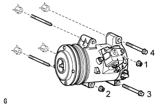
Using an E8 "TORX" socket wrench, install the with pulley compressor assembly with the 2 stud bolts.
- Torque:
- 10 N*m { 102 kgf*cm, 7 ft.*lbf }
-
Install the 2 bolts and 2 nuts.
- Torque:
- 25 N*m { 250 kgf*cm, 18 ft.*lbf }
Note
Tighten the nuts and bolts in the order shown in the illustration to install the with pulley compressor assembly.
-
Connect the connector.
-
-
CONNECT DISCHARGE HOSE SUB-ASSEMBLY
-
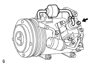
Remove the attached vinyl tape from the hose.
-
Sufficiently apply compressor oil to a new O-ring and the fitting surface of the with pulley compressor assembly.
Compressor oil ND-OIL 8 or equivalent -
Install the O-ring to the discharge hose sub-assembly.
-
Connect the discharge hose sub-assembly to the with pulley compressor assembly with the bolt.
- Torque:
- 9.8 N*m { 100 kgf*cm, 87 in.*lbf }
-
-
CONNECT SUCTION TUBE SUB-ASSEMBLY B
-
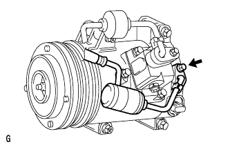
Remove the attached vinyl tape from the tube sub-assembly B.
-
Sufficiently apply compressor oil to a new O-ring and the fitting surface of the with pulley compressor assembly.
Compressor oil ND-OIL 8 or equivalent -
Install the O-ring to the cooler suction tube sub-assembly B.
-
Connect the suction tube sub-assembly B to the with pulley compressor assembly with the bolt.
- Torque:
- 9.8 N*m { 100 kgf*cm, 87 in.*lbf }
-
-
INSTALL EXHAUST MANIFOLD SUB-ASSEMBLY LH
for 1UR-FE: Click here
for 1UR-FSE: Click here
-
CONNECT CABLE TO NEGATIVE BATTERY TERMINAL
Note
When disconnecting the cable, some systems need to be initialized after the cable is reconnected Click here.
-
INSTALL COWL TOP VENTILATOR LOUVER
-

for LHD:
Install the 6 clips and cowl top ventilator louver RH.
Note
If the cowl top ventilator louver RH is not properly installed, water may leak into the engine room and cause malfunctions. Therefore, make sure the cowl top ventilator louver RH is installed properly.
-

for RHD:
Install the 6 clips and cowl top ventilator louver LH.
Note
If the cowl top ventilator louver LH is not properly installed, water may leak into the engine room and cause malfunctions. Therefore, make sure the cowl top ventilator louver LH is installed properly.
-
-
ADD COMPRESSOR OIL
-
When performing work on air conditioning parts, follow the oil guidelines below in order to protect the cooler compressor.
Part and Condition Oil Level (cc) Work Procedure Compressor replacement -100 to -120 Drain oil from new compressor Condenser replacement 35 to 55 Fill oil into replacement part Evaporator replacement 40 to 60 A/C pipe replacement High pressure 5 to 25 Low pressure When discharging refrigerant gas quickly 30 to 50 While applying vacuum, use manifold gauge to fill oil from low pressure side valve
-
-
CHARGE REFRIGERANT
- SST
- 09985-20010 ( 09985-02130, 09985-02150, 09985-02090, 09985-02110, 09985-02010, 09985-02050, 09985-02060, 09985-02070 )
-
Perform vacuum purging using a vacuum pump.
-
Charge refrigerant HFC-134a (R134a).
Standard Destination Air Conditioning Type Refrigerant Charging Amount except G.C.C Countries w/o Rear Cooler 550 +/-50 g (19.4 +/-1.8 oz.) w/ Rear Cooler 700 +/-30 g (24.7 +/-1.1 oz.) G.C.C Countries w/o Rear Cooler 750 +/-30 g (26.5 +/-1.1 oz.) w/ Rear Cooler 1000 +/-50 g (35.3 +/-1.8 oz.) 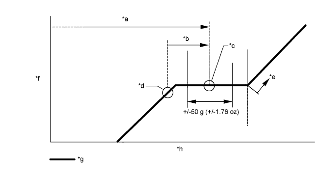
Text in Illustration *a Amount to be charged *b Charge 100 g (3.53 oz) *c Mean value in proper range *d Point where bubbles disappear *e Overcharged *f Pressure *g Sub-cool system *h Refrigerant amount Note
-
Do not operate the cooler compressor before charging refrigerant as the cooler compressor will not work properly without any refrigerant, and will overheat.
-
Approximately 200 g (7.05 oz.) of refrigerant may need to be charged after bubbles disappear. The refrigerant amount should be checked by measuring its quantity, and not with the sight glass.
-
-
WARM UP ENGINE
-
Warm up the engine at less than 1850 rpm for 2 minutes or more after charging the refrigerant.
Note
Be sure to warm up the compressor when turning the A/C switch ON after removing and installing the cooler refrigerant lines (including the compressor) to prevent damage to the compressor.
-
-
CHECK FOR LEAKAGE OF REFRIGERANT
-
After recharging the refrigerant gas, check for refrigerant gas leakage using a halogen leak detector.
-
Perform the operation under these conditions:
-
Stop the engine.
-
Secure good ventilation (the halogen leak detector may react to volatile gases other than refrigerant, such as evaporated gasoline or exhaust gas).
-
Repeat the test 2 or 3 times.
-
Make sure that some refrigerant remains in the refrigeration system.
Tech Tips
When compressor is off:
approximately 392 to 588 kPa (4 to 6 kgf/cm2, 57 to 85 psi)
-
-
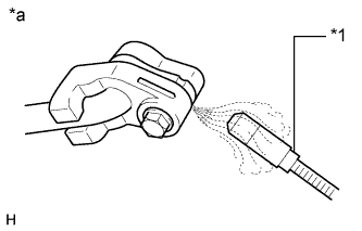
Text in Illustration *1 Halogen Leak Detector *a Check for Leakage Using a halogen leak detector, check the refrigerant line for leakage.
-
If a gas leak is not detected on the drain hose, remove the blower motor control (blower resistor) from the cooling unit. Insert the halogen leak detector sensor into the unit and perform the test.
-
Disconnect the connector and wait for approximately 20 minutes. Bring the halogen leak detector close to the pressure switch and perform the test.
-
-
INSPECT FOR EXHAUST GAS LEAK
-
If gas is leaking, tighten the areas necessary to stop the leak. Replace the damaged parts as necessary.
-
-
PLACE FRONT WHEELS FACING STRAIGHT AHEAD
-
CHECK AND ADJUST FRONT WHEEL ALIGNMENT