FRONT BRAKE (for 6-Pot Caliper) INSTALLATION

Tech Tips
-
Use the same procedure for the RH and LH sides.
-
The following procedure is for the LH side.
-
INSTALL FRONT DISC
Note
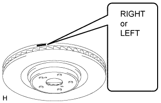
Be sure to check the identification mark when installing the disc.
Item Identification mark LH LEFT RH RIGHT
-
Align the matchmarks and install the front disc.
Note
When replacing the front disc with a new one, select the installation position where the front disc has minimal runout.
-
-
INSTALL FRONT DISC BRAKE CYLINDER ASSEMBLY
-
Install the front disc brake cylinder assembly with the new 2 bolts.
- Torque:
- 135 N*m { 1377 kgf*cm, 100 ft.*lbf }
-
-
INSTALL FRONT DISC BRAKE PAD
-
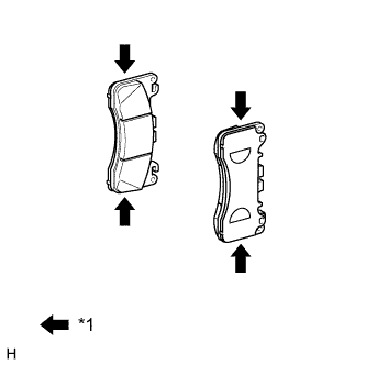
Text in Illustration *1 Disc brake grease Apply a light coat of disc brake grease to the front disc brake pads as shown in the illustration.
Note
-
When applying the disc brake grease, use the grease enclosed with a front disc brake pad kit or supplied grease (Part No. 90998-94072) or equivalent.
-
There should be no oil or grease on the friction surfaces of the pads and the disc.
-
-
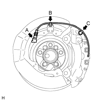
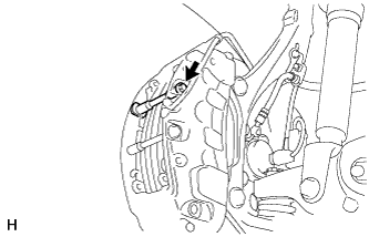
Connect the pad wear indicator wire connector (labeled A).
-
Attach the clamp (labeled B) and bleeder plug cap (labeled C).
-
Install the pad wear indicator wire and retainer to the inner pad.
-
Install the front disc brake pads to the front disc brake cylinder assembly.
-
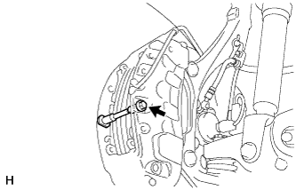
Install the pad guide tie rod (lower) with the bolt.
- Torque:
- 30 N*m { 306 kgf*cm, 22 ft.*lbf }
-
Install the pad guide tie rod (upper) with the bolt.
- Torque:
- 30 N*m { 306 kgf*cm, 22 ft.*lbf }
-
Install the anti-rattle spring to the front disc brake cylinder assembly.
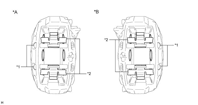
Text in Illustration *A LH Side *B RH Side *1 Pad Guide Tie Rod *2 Anti-rattle Spring Note
Securely install the anti-rattle spring in the correct position and facing the correct direction.
-
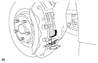
While holding the anti-rattle spring, insert the pad guide pin (lower) into the front disc brake cylinder assembly as shown in the illustration.
-
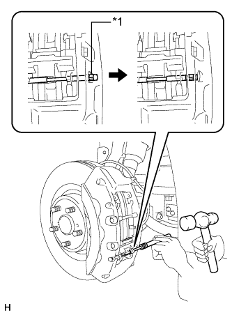
Text in Illustration *1 Ring Using a pin punch (5 mm) and hammer, install the pad guide pin (lower) to the front disc brake cylinder assembly.
Note
-
Do not damage the disc brake cylinder surface.
-
Securely attach the ring of the pad guide pin to the front disc brake cylinder assembly.
-
Make sure that the front disc brake anti-rattle spring is securely attached to the grooves of the front disc brake pad guide pin.
-
-
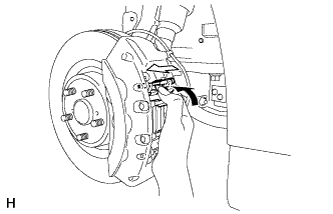
While holding the anti-rattle spring, insert the pad guide pin (upper) into the front disc brake cylinder assembly as shown in the illustration.
-
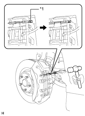
Text in Illustration *1 Ring Using a pin punch (5 mm) and hammer, install the pad guide pin (upper) to the front disc brake cylinder assembly.
Note
-
Do not damage the disc brake cylinder surface.
-
Securely attach the ring of the pad guide pin to the front disc brake cylinder assembly.
-
Make sure that the front disc brake anti-rattle spring is securely attached to the grooves of the front disc brake pad guide pin.
-
-
-
CONNECT FRONT FLEXIBLE HOSE
-
Connect the front flexible hose and a new gasket to the front disc brake cylinder assembly with a new union bolt.
- Torque:
- 39 N*m { 400 kgf*cm, 29 ft.*lbf }
Note
Install the flexible hose lock so that it fits securely in the lock hole in the disc brake cylinder assembly.
-
-
CONNECT CABLE TO NEGATIVE BATTERY TERMINAL
Note
When disconnecting the cable, some systems need to be initialized after the cable is reconnected Click here.
-
INSTALL COWL TOP VENTILATOR LOUVER RH
-

Install the 6 clips and cowl top ventilator louver RH.
Note
Be sure to install the cowl top ventilator louver RH properly. If it is not installed properly, water may enter the engine room and cause malfunctions.
-
-
BLEED BRAKE LINE
-
Bleed brake line.
-
Remove the brake master cylinder reservoir filler cap assembly.
-
Add brake fluid into the reservoir between MAX and MIN level on the brake fluid reservoir.
Brake fluid SAE J1703 or FMVSS No. 116 DOT3 -
Connect the intelligent tester to the DLC3 and turn the power switch on (IG).
-
Turn the intelligent tester on and enter the following menus: Chassis / ABS/VSC/TRC / Utility / Air Bleeding.
-
Select the "Usual air bleeding / All Line" and bleed brake line according to the intelligent tester display.
-
After air bleeding, tighten each bleeder plug.
- Torque:
- for Front Brake (except 6-pot caliper)
- 11 N*m { 110 kgf*cm, 8 ft.*lbf }
- for Front Brake (6-pot caliper)
- 19 N*m { 194 kgf*cm, 14 ft.*lbf }
- for Rear Brake
- 11 N*m { 110 kgf*cm, 8 ft.*lbf }
-
-
Clear the DTCs Click here.
-
Turn the intelligent tester off and turn the power switch off.
-
Inspect for brake fluid leaks.
-
Adjust the brake fluid level in the reservoir Click here.
-
-
INSTALL FRONT WHEEL
- Torque:
- 140 N*m { 1050 kgf*cm, 76 ft.*lbf }
-
CLEAR DTC
-
CHECK FOR DTC
-
If any DTC is output, perform the troubleshooting for that DTC Click here.
-