BRAKE ACTUATOR (for RHD) INSTALLATION

Note
While the battery is connected, even if the engine switch is off, the brake control system activates when the brake pedal is depressed or the door courtesy switch turns on. Therefore during servicing of the brake system components, do not operate the brake pedal and open/close the doors while the battery is connected.
-
INSTALL BRAKE ACTUATOR
Note
Do not remove the hole plug before installing a new brake actuator because the brake actuator is filled with brake fluid.
-
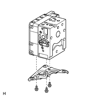
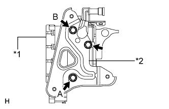
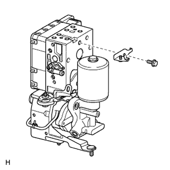
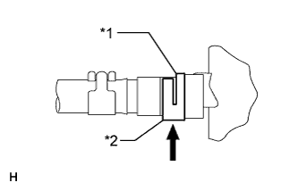
Text in Illustration *1 Brake Actuator *2 No. 3 Bracket Install the No. 3 brake actuator bracket to the brake actuator with the 3 bolts.
- Torque:
- 9.3 N*m { 95 kgf*cm, 82 in.*lbf }
Note
After temporarily installing either bolt A or B, tighten the remaining bolts.
-
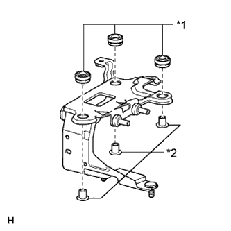
Text in Illustration *1 Cushion *2 Spacer 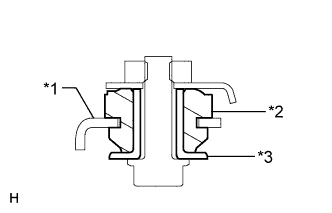
Text in Illustration *1 Bracket *2 Cushion *3 Spacer Install the 3 cushions and 3 spacers to the bracket.
-
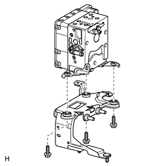
Install the brake actuator bracket to the brake actuator with the 3 bolts.
- Torque:
- 9.2 N*m { 94 kgf*cm, 81 in.*lbf }
-
-
INSTALL BRAKE ACCUMULATOR PUMP
-
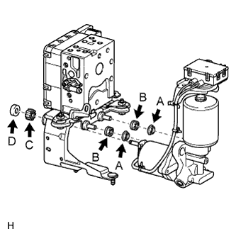
Install the brake booster pump collars (labeled A) and brake booster pump bushes (labeled B) to the brake accumulator pump.
-
Text in Illustration *1 Actuator Bracket *2 Brake Accumulator Pump *3 Collar (A) Install the brake accumulator pump to the brake actuator bracket.
Note
After installing the brake accumulator pump, make sure the collar has not fallen off.
-
Text in Illustration *1 Brake Accumulator Pump *2 Clamp (D) *3 Bush (C) Install the brake booster pump bush (labeled C) and a new brake actuator bracket clamp (labeled D) to the brake accumulator pump.
Note
Make sure to securely insert the brake accumulator pump until the claws of the clamp are attached.
-
-
INSTALL NO. 4 BRAKE ACTUATOR BRACKET
-
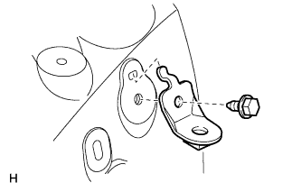
Install the No. 4 brake actuator bracket to the brake actuator with the bolt.
- Torque:
- 18 N*m { 184 kgf*cm, 13 ft.*lbf }
-
-
CONNECT BRAKE ACCUMULATOR PUMP CONNECTOR BOX
-
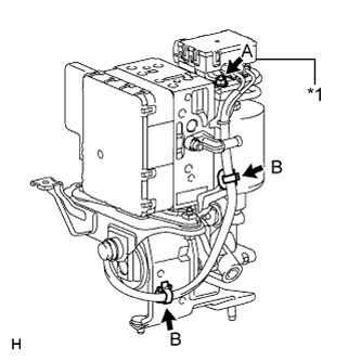
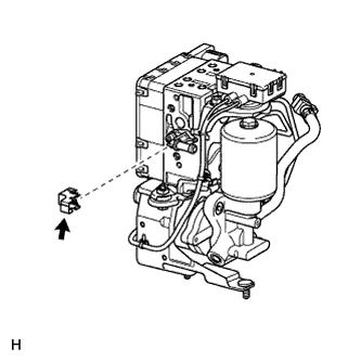
Text in Illustration *1 Connector Box Connect the brake accumulator pump connector box as follows:
-
Install the connector box with the nut (labeled A).
- Torque:
- 6.0 N*m { 61 kgf*cm, 53 in.*lbf }
-
Attach the 2 wiring harness clamps (labeled B).
-
-
-
INSTALL NO. 3 BRAKE ACTUATOR TUBE
Note
-
Do not damage the No. 3 brake actuator tube, brake actuator and brake accumulator pump.
-
When installing the No. 3 brake actuator tube, hold the tube, brake actuator and brake accumulator pump securely.
-
When tightening the nut, make sure that other parts do not move with the nut.
-
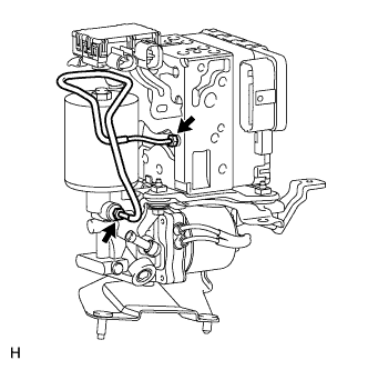
Using a union nut wrench, connect the No. 3 brake actuator tube.
- Torque:
- 15 N*m { 155 kgf*cm, 11 ft.*lbf }
Note
Use the formula to calculate special torque values for situations where a union nut wrench is combined with a torque wrench Click here.
-
-
INSTALL NO. 2 BRAKE ACTUATOR HOSE
-
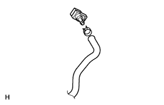
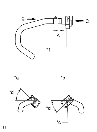
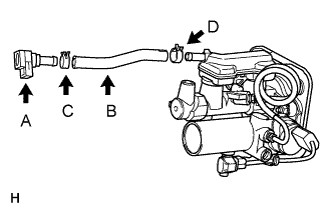
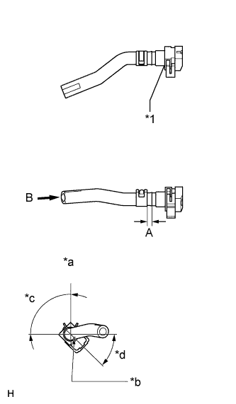
Install the reservoir connector to the No. 2 brake actuator hose with the hose clip as shown in the illustration.
Length "A" 4.0 to 7.0 mm (0.158 to 0.276 in.) Text in Illustration *1 Reservoir Connector *a View B *b View C *c Paint Mark *d 30°to 60° -
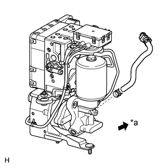
Text in Illustration *a Front With the paint mark on the hose's tip facing the bottom of the vehicle, install the No. 2 brake actuator hose to the brake accumulator pump with the hose clip.
Tech Tips
Install the hose clip so that its claws face the front of the vehicle.
Note
When inserting the hose, be careful that there is no excessive weight applied to the union of the brake accumulator pump (especially in the union rotation direction).
-
-
INSTALL BRAKE ACTUATOR PROTECTOR
-
Install the protector.
-
-
INSTALL NO. 1 BRAKE ACTUATOR HOSE
-
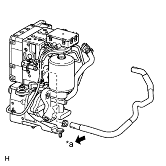
Text in Illustration *a Rear With the paint mark on the hose's tip facing the bottom of the vehicle, install the No. 1 brake actuator hose to the brake actuator with the hose clip.
Tech Tips
Install the hose clip so that its claws face the rear of the vehicle.
Note
When inserting the hose, be careful that there is no excessive weight applied to the union of the brake actuator (especially in the union rotation direction).
-
-
INSTALL NO. 5 BRAKE ACTUATOR BRACKET
-
Install the No. 5 brake actuator bracket to the body with the bolt.
- Torque:
- 11 N*m { 112 kgf*cm, 8 ft.*lbf }
-
-
INSTALL BRAKE ACTUATOR AND BRAKE ACCUMULATOR PUMP ASSEMBLY
-
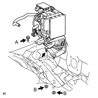
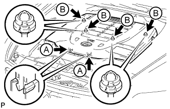
Install the brake actuator and brake accumulator pump to the body with the bolt (labeled A) and 2 nuts (labeled B).
Tech Tips
First insert the bracket bottom's longer stud bolt (vehicle outer side, labeled C) into the body.
Note
-
Do not damage the brake tubes.
-
When installing the brake actuator and brake accumulator pump to the vehicle, do not hold the connector, harness, hose or tube parts.
-
Do not drop the brake actuator and brake accumulator pump. Do not use parts that have been dropped.
- Torque:
- 20 N*m { 204 kgf*cm, 15 ft.*lbf }
-
-
Connect the front fender liner rear side.
-
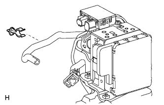
Connect the No. 1 brake actuator hose to the body with the clamp.
-
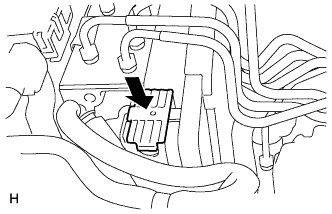
Connect the brake actuator connector.
Note
-
Before connecting the vehicle wire harnesses, make sure that the connector faces are free of foreign matter.
-
Make sure that the connector is locked securely.
-
-
-
CONNECT BRAKE TUBE
-
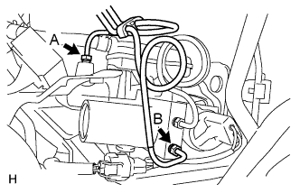
Using a union nut wrench, connect the No. 1 (labeled A) and No. 2 (labeled B) brake actuator tubes.
- Torque:
- 15 N*m { 155 kgf*cm, 11 ft.*lbf }
Note
-
Do not damage the No. 1 and No. 2 brake actuator tubes.
-
Use the formula to calculate special torque values for situations where a union nut wrench is combined with a torque wrench Click here.
-
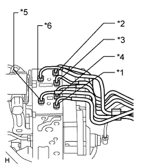
Set each brake tube to the correct positions on the brake actuator as shown in the illustration.
-
*1: To FR RH
-
*2: To FR LH
-
*3: To RR RH
-
*4: To RR LH
-
*5: From Master Cylinder
-
*6: From Stroke Simulator
-
-
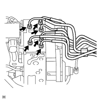
Using a union nut wrench, connect the 6 brake tubes.
- Torque:
- 15 N*m { 155 kgf*cm, 11 ft.*lbf }
Note
Use the formula to calculate special torque values for situations where a union nut wrench is combined with a torque wrench Click here.
-
-
INSTALL FRONT WHEEL
- Torque:
- 140 N*m { 1428 kgf*cm, 103 ft.*lbf }
-
INSTALL RESERVOIR BRACKET
-
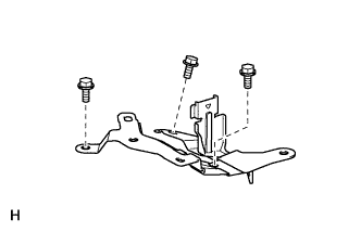
Install the reservoir bracket with the 3 bolts.
- Torque:
- 8.5 N*m { 87 kgf*cm, 75 in.*lbf }
-
-
INSTALL NO. 1 RESERVOIR HOSE
-
Install the reservoir connector (labeled A) to the No. 1 reservoir hose (labeled B) with the hose clip (labeled C) as shown in the illustration.
Length "A" 4.0 to 7.0 mm (0.158 to 0.276 in.) Text in Illustration *1 Reservoir Connector *a View B *b Paint Mark *c 75° to 105° *d 30° to 60° -
With the paint mark on the hose's tip facing the top of the vehicle, install the No. 1 reservoir hose (labeled B) to the master cylinder with the hose clip (labeled D).
Tech Tips
Install the hose clip so that its claws face the top of the vehicle.
-
-
INSTALL BRAKE MASTER CYLINDER RESERVOIR ASSEMBLY
-
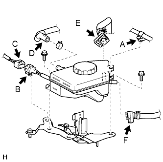
Connect the No. 1 reservoir hose (labeled F) and No. 2 brake actuator hose (labeled E) to the reservoir. The reservoir connector connecting procedure must be followed as described below:
-
Remove the foreign matter entry prevention plastic bags.
Note
Check that there is no damage or foreign objects on the connected part of the reservoir and reservoir connectors.
-
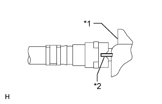
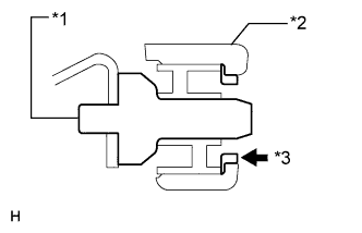
Text in Illustration *1 Reservoir *2 Rib Insert the reservoir connector to the reservoir until the reservoir connector makes a "click" sound, so that the reservoir connector tip's groove is aligned with the reservoir's rib.
-
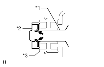
Text in Illustration *1 Claw *2 Lock Securely set the lock of the reservoir connector.
-
Check that the reservoir connector lock's claw is securely attached.
-
-
With the paint mark on the hose's tip facing the top of the vehicle, connect the No. 1 brake actuator hose (labeled D) to the reservoir with the hose clip.
Tech Tips
Install the hose clip so that its claws face the top of the vehicle.
-
Connect the brake fluid level warning switch connector (labeled C), and then attach the connector clamp (labeled B) to the reservoir bracket.
-
Install the brake fluid reservoir with the 2 bolts.
- Torque:
- 8.5 N*m { 87 kgf*cm, 75 in.*lbf }
-
Connect the wire harness clamp (labeled A) to the reservoir.
-
-
CONNECT NO. 3 RELAY BLOCK
-
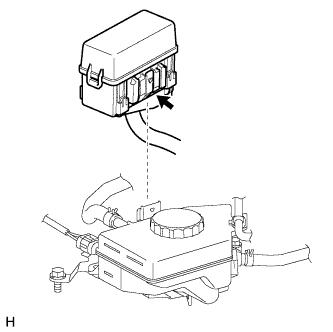
Install the No. 3 relay block to the reservoir bracket.
Note
Check that the claw of the No. 3 relay block is securely attached to the reservoir bracket.
-
-
INSTALL SKID CONTROL ECU BRACKET
-
INSTALL SKID CONTROL ECU
-
CONNECT CABLE TO NEGATIVE BATTERY TERMINAL
Note
-
Make sure that the 2 accumulator pump connectors are disconnected.
-
When disconnecting the cable, some systems need to be initialized after the cable is reconnected Click here.
-
-
BLEED BRAKE SYSTEM
-
CLEAR THE DTC
-
PERFORM LINEAR VALVE OFFSET LEARNING
-
When the brake actuator is replaced, perform the linear valve offset learning Click here.
-
-
CHECK FOR DTC
-
If any DTC is set, perform the troubleshooting for the DTC Click here.
-
-
READ VALUE OF ACCUMULATOR PRESSURE SENSOR OUTPUT VOLTAGE
Tech Tips
If removing and installing the No. 3 brake actuator tube, check for a brake fluid leak from the No. 3 tube connection area by monitoring the accumulator pressure sensor output value from the brake actuator. Directly checking for a brake fluid leak from the No. 3 tube connection area is difficult.
-
Turn the engine switch off.
-
Connect the intelligent tester to the DLC3.
-
Turn the engine switch on (IG).
-
Operate the intelligent tester according to the display and select "DATA LIST".
Skid control ECU: Tester Display Measurement Item/Range Normal Condition Diagnostic Note Accumulator Pressure Sensor Accumulator pressure sensor / min.: 0 V, max.: 5 V Specified value: 2.6 to 3.8 V - -
Depress the brake pedal 4 or 5 times to operate the pump motor, and check the output value on the intelligent tester with the motor stopped (not braking).
OK Accumulator pressure sensor's output voltage drops 0.2 V or less for 30 seconds. If the voltage drops more than 0.2 V, there may be a brake fluid leak from the No. 3 brake actuator tube connection area. Remove the brake actuator and brake accumulator pump, and then repeat the procedures above from the retightening of the 2 union nuts of the No. 3 brake actuator tube.
- Torque:
- 15 N*m { 155 kgf*cm, 11 ft.*lbf }
Note
Use the formula to calculate special torque values for situations where a union nut wrench is combined with a torque wrench Click here.
-
-
INSTALL COWL TOP VENTILATOR LOUVER SUB-ASSEMBLY
-
INSTALL COWL TOP VENTILATOR LOUVER LH
-

for LHD:
Install the 6 clips and cowl top ventilator louver RH.
Note
If the cowl top ventilator louver RH is not properly installed, water may leak into the engine room and cause malfunctions. Therefore, make sure the cowl top ventilator louver RH is installed properly.
-

for RHD:
Install the 6 clips and cowl top ventilator louver LH.
Note
If the cowl top ventilator louver LH is not properly installed, water may leak into the engine room and cause malfunctions. Therefore, make sure the cowl top ventilator louver LH is installed properly.
-
-
INSTALL V-BANK COVER SUB-ASSEMBLY
-
Slide the cover from the vehicle front toward the rear of the vehicle to attach the 2 clips labeled A, and then attach the 4 clips labeled B to install the V bank cover sub-assembly.
Note
-
Make sure the clips are attached securely.
-
Attaching the clips forcefully or hitting the top of the clips may damage them.
-
When attaching the clips labeled A, be sure to slide the cover from the front of the vehicle toward the rear of the vehicle.
-
-