REAR WHEEL ALIGNMENT ADJUSTMENT

-
INSPECT TIRE
-
Inspect the tires Click here.
-
-
MEASURE VEHICLE HEIGHT (for 2WD)
-
Measure the vehicle height for coil suspension Click here.
-
Measure the vehicle height for air suspension Click here.
-
-
MEASURE VEHICLE HEIGHT (for AWD)
-
Measure the vehicle height Click here.
-
-
INSPECT TOE-IN
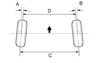
Standard toe-in Item Standard toe-in Toe-in
(total)
A + B: 0°15' +/-10' (0.25°+/-0.16°)
C - D: 3.0 +/-2.0 mm (0.12 +/-0.08 in.)
-
If the toe-in is not within the specified range, inspect the suspension parts and replace if necessary.
-
-
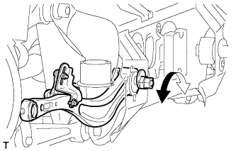
ADJUST TOE-IN
-
Loosen the toe adjust cam nut.
-
Turn the adjust cams by an equal amount to adjust toe-in.
Tech Tips
-
Try to adjust the toe-in to the center value.
-
The toe-in will change by the following specification corresponding to each graduation of the cam:
Approximately 4.8 mm (0.189 in.)
-
-
Tighten the nut.
- Torque:
- 60 N*m { 612 kgf*cm, 44 ft.*lbf }
-
-
INSPECT CAMBER
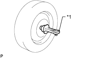
Text in Illustration *1 Camber-Caster-Kingpin Gauge
-
Install a camber-caster-kingpin gauge or put the wheels on a wheel alignment tester.
-
Inspect the camber.
Standard camber inclination (unloaded vehicle) Item Camber Inclination w/o Air Suspension Camber
Left-right error
-1°38' +/-45' (-1.63° +/- 0.75°)
30' (0.50°) or less
w/ Air Suspension
(for 2WD)
Camber
Left-right error
-1°50' +/-45' (-1.83° +/- 0.75°)
30' (0.50°) or less
w/ Air Suspension
(for AWD)
Camber
Left-right error
-1°41' +/-45' (-1.68° +/- 0.75°)
30' (0.50°) or less
Sports Package Camber
Left-right error
-1°59' +/-45' (-1.98° +/- 0.75°)
30' (0.50°) or less
-
If the measured value is not within the specified range, inspect the suspension parts for damage and wear. Replace parts as necessary because camber cannot be properly adjusted with any damaged or worn parts.
-
-
-
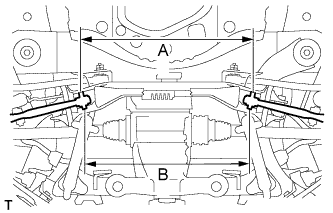
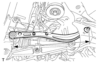
INSPECT REAR SUSPENSION
-
Inspect the rear suspension member.
-
Measure the distance between the centers of the installation bolts of the rear No. 2 suspension arm assembly LH and RH.
Standard length Length A Length B 635.0 mm (25.000 in.) 588.0 mm (23.150 in.) Tech Tips
If the distance is not within the specified range, replace the rear suspension member.
-
Visually inspect the press holes on the installation area of the rear upper No. 2 control arm assembly.
Standard length The holes are not deformed. Tech Tips
If the holes are deformed, replace the rear suspension member.
-
-
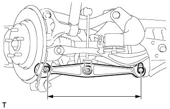
Inspect the rear No. 1 suspension arm.
-
Measure the distance between the centers of the 2 installation bolts of the rear No. 1 suspension arm.
Standard length 361.3 to 362.1 mm (14.224 to 14.256 in.) Tech Tips
If the distance is not within the specified range, replace the rear No. 1 suspension arm.
-
-
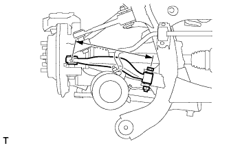
Inspect the rear No. 2 suspension arm.
-
Measure the distance between the centers of the 2 installation bolts of the rear No. 2 suspension arm.
Standard length 426.8 to 427.6 mm (16.803 to 16.835 in.) Tech Tips
If the distance is not within the specified range, replace the rear No. 2 suspension arm.
-
-
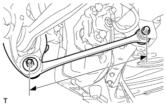
Inspect the rear upper No. 1 control arm.
-
Measure the distance between the centers of the installation bolt of the rear upper No. 1 control arm and the ball joint stud.
Standard length 208.5 to 209.3 mm (8.209 to 8.240 in.) Tech Tips
If the distance is not within the specified range, replace the rear upper No. 1 control arm.
-
-
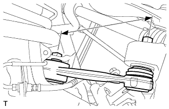
Inspect the rear upper No. 2 control arm.
-
Measure the distance between the centers of the installation bolt of the rear upper No. 2 control arm and the ball joint stud.
Standard length 329.2 to 330.0 mm (12.961 to 12.992 in.) Tech Tips
If the distance is not within the specified range, replace the rear upper No. 2 control arm.
-
-
Inspect the toe control link.
-
Measure the distance between the centers of the installation bolt of the toe control link and the ball joint stud.
Standard length 472.6 to 473.6 mm (18.606 to 18.646 in.) Tech Tips
If the distance is not within the specified range, replace the toe control link.
-
-
Inspect and adjust toe-in and camber.
-
Inspect toe-in and camber.
-
If the values are not within the specified range, adjust the installation bolt holding the rear suspension member to the vehicle body, or the bolt holding the upper control arm and rear suspension arm so that the values fall within the specified range.
-
-
-
-
REPLACE REAR SUSPENSION ARM ATTACHMENT SUB-ASSEMBLY
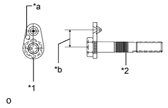
Text in Illustration *1 Toe Adjust Plate *2 Rear Suspension Attachment *a Stamping Position *b Dimension A
-
When rear suspension member is not replaced:
-
Use the same stamping No. as the parts that were removed from the left and right side of the vehicle.
-
-
When rear suspension member is replaced:
-
Use stamping No. 1 for the parts that were removed from the left and right side of the vehicle.
Part No. information Stamping No. Part No. (Rear suspension attachment) Part No. (Toe adjust plate) Dimension A 1 48709-50040 48452-50010 23 mm (0.906 in.) 2 48709-50050 48452-50020 21 mm (0.827 in.) 3 48709-50060 48452-50030 25 mm (0.985 in.)
-
-
-
REMOVE COWL TOP VENTILATOR LOUVER
-

for LHD:
Remove the 6 clips and cowl top ventilator louver RH.
-

for RHD:
Remove the 6 clips and cowl top ventilator louver LH.
-
-
PRECAUTION
Note
After turning the engine switch off, waiting time may be required before disconnecting the cable from the battery terminal. Therefore, make sure to read the disconnecting the cable from the battery terminal notice before proceeding with work Click here.
-
DISCONNECT CABLE FROM NEGATIVE BATTERY TERMINAL
Note
-
When disconnecting the cable, some systems need to be initialized after the cable is reconnected Click here.
-
Disconnect the cable from the negative battery terminal for 2 seconds or more.
-
-
CONNECT CABLE TO NEGATIVE BATTERY TERMINAL
-
INSTALL COWL TOP VENTILATOR LOUVER
-
for LHD:
Install the 6 clips and cowl top ventilator louver RH.
Note
If the cowl top ventilator louver RH is not properly installed, water may leak into the engine room and cause malfunctions. Therefore, make sure the cowl top ventilator louver RH is installed properly.
-
for RHD:
Install the 6 clips and cowl top ventilator louver LH.
Note
If the cowl top ventilator louver LH is not properly installed, water may leak into the engine room and cause malfunctions. Therefore, make sure the cowl top ventilator louver LH is installed properly.
-
-
PERFORM YAW RATE AND DECELERATION SENSOR ZERO POINT CALIBRATION
-
Perform the yaw rate and deceleration sensor zero point calibration Click here.
-
-
INITIALIZE ROTATION ANGLE SENSOR AND CALIBRATE TORQUE SENSOR ZERO POINT
-
Initialize the rotation angle sensor and calibrate torque sensor zero point Click here.
-