AUTOMATIC TRANSMISSION ASSEMBLY INSTALLATION

-
INSTALL TRANSFER ASSEMBLY
-
Using wooden blocks or equivalent, raise the transfer assembly so that it is level with the automatic transmission, align the knock pins with the knock pin holes and install the transfer.
Note
-
Be careful not to damage the oil seal.
-
Be careful not to drop the transfer assembly.
-
Be careful to prevent oil from leaking.
-
Be sure to perform this procedure with several people as the transfer assembly is very heavy.
-
-
Install the 11 bolts.
- Torque:
- 23 N*m { 229 kgf*cm, 17 ft.*lbf }
-
-
INSPECT TORQUE CONVERTER ASSEMBLY
-
INSTALL TORQUE CONVERTER ASSEMBLY
-
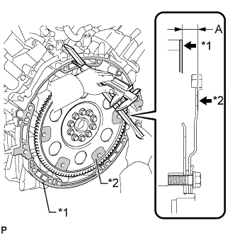
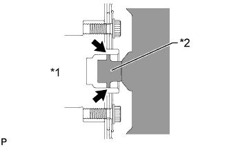
Using a vernier caliper and straightedge, measure distance A between the surface of the engine that contacts the transmission and the surface of the drive plate that contacts the torque converter.
Text in Illustration *1 Engine Surface *2 Drive Plate Surface -
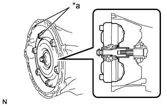
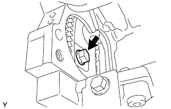
Text in Illustration *a Matchmark Align the matchmarks on the transmission case and torque converter, and then engage the splines of the input shaft and turbine runner.
-
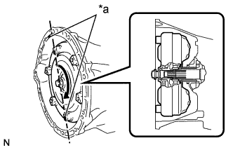
Text in Illustration *a Matchmark Mesh the splines of the stator shaft and stator while turning the torque converter.
Tech Tips
Turn the torque converter approximately 180°.
-
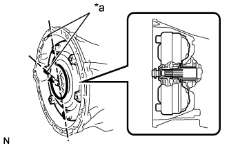
Text in Illustration *a Matchmark Turn the torque converter and align the matchmarks on the torque converter and transmission case to fit the key of the oil pump drive gear into the slot on the torque converter.
Note
Do not push on the torque converter when aligning the matchmarks.
-
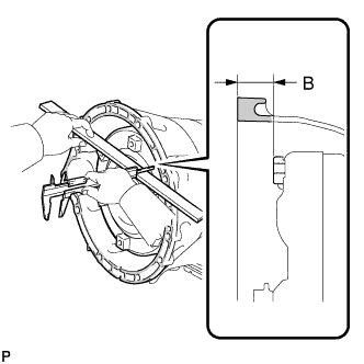
Using a vernier caliper and straightedge, measure distance B shown in the illustration and check that distance B is more than distance A, which was measured in the first step.
Standard B = A + 1 mm (0.0394 in.) or more
-
-
INSTALL AUTOMATIC WITH TRANSFER TRANSMISSION ASSEMBLY
Text in Illustration *1 Crankshaft *2 Torque Converter Centerpiece
-
Apply clutch spline grease to the surface of the crankshaft that contacts the torque converter centerpiece.
Clutch spline grease Toyota Genuine Clutch Spline Grease or equivalent Maximum grease amount Approximately 1 g (0.0353 oz) -
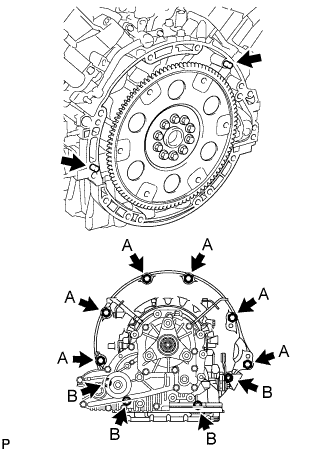
While keeping the engine and automatic transmission assembly horizontal, align the knock pins with the holes in the automatic transmission assembly and install the 10 bolts shown in the illustration.
- Torque:
- for Bolt A (17 mm head bolt)
- 71 N*m { 724 kgf*cm, 52 ft.*lbf }
- for Bolt B (14 mm head bolt)
- 37 N*m { 377 kgf*cm, 27 ft.*lbf }
Note
-
Insert the knock pins into the knock pin holes securely so that the end face of the transmission assembly fits close against the engine assembly before tightening the bolts.
-
Do not use excessive force to pry on the transmission assembly.
-
Confirm that the 2 knock pins are installed to the engine cylinder block before installing the transmission.
-
-
INSTALL DRIVE PLATE & TORQUE CONVERTER SETTING BOLT
-
Turn the crankshaft to gain access to the installation locations of the 6 torque converter setting bolts and install each bolt while holding the crankshaft pulley bolt with a wrench.
- Torque:
- 48 N*m { 489 kgf*cm, 35 ft.*lbf }
Note
First install the black-colored bolt, and then the remaining 5 silver colored bolts.
-
-
CONNECT WIRE HARNESS AND CONNECTOR
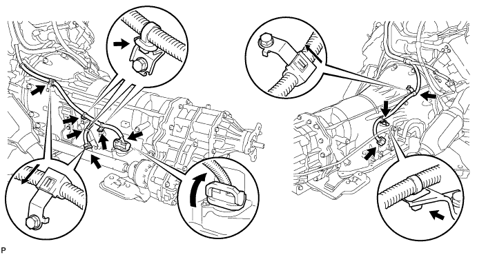
-
Connect the park/neutral position switch connector and transmission wire connector.
Tech Tips
Push up the lever until the claw of the transmission wire connector makes a connection sound.
-
Attach the 6 harness clamps and connector clamp to the automatic transmission.
-
-
INSTALL FRONT PROPELLER SHAFT ASSEMBLY
-
INSTALL REAR NO. 1 ENGINE MOUNTING INSULATOR AND REAR NO. 2 ENGINE MOUNTING INSULATOR
-
Install the rear No. 1 engine mounting insulator and rear No. 2 engine mounting insulator with the 4 bolts.
- Torque:
- 30 N*m { 306 kgf*cm, 22 ft.*lbf }
-
-
INSTALL REAR NO. 4 ENGINE MOUNTING INSULATOR
-
Install the rear No. 4 engine mounting insulator with the 2 bolts.
- Torque:
- 30 N*m { 306 kgf*cm, 22 ft.*lbf }
-
-
INSTALL REAR ENGINE MOUNTING MEMBER
-
Install the rear engine mounting member and rear No. 3 engine mounting insulator with the 5 nuts.
- Torque:
- 38 N*m { 387 kgf*cm, 28 ft.*lbf }
-
-
INSTALL NO. 1 OIL COOLER TUBE SUB-ASSEMBLY
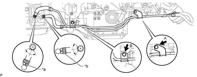
Text in Illustration *a Paint Mark (Red) *b Paint Mark (Blue)
-
Temporarily install the No. 1 oil cooler tube sub-assembly with the 2 bolts.
-
Tighten the bolt for bracket A, make sure the stopper of bracket B is securely in place against the engine oil pan, and then tighten the bolt for bracket B.
- Torque:
- 14 N*m { 143 kgf*cm, 10 ft.*lbf }
-
Connect the 2 oil cooler hoses with the 2 clips as shown in the illustration.
-
-
INSTALL STARTER ASSEMBLY
-
INSTALL EXHAUST MANIFOLD SUB-ASSEMBLY RH
-
INSTALL EXHAUST MANIFOLD SUB-ASSEMBLY LH
-
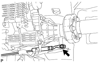
INSTALL TRANSMISSION CONTROL SHAFT LEVER RH
-
Install the transmission control shaft lever together with the floor shift gear shifting rod sub-assembly with the nut.
- Torque:
- 16 N*m { 160 kgf*cm, 12 ft.*lbf }
-
-
INSTALL ENGINE AND TRANSMISSION
-
ADJUST SHIFT LEVER POSITION
-
Remove the nut and disconnect the shifting rod.
-
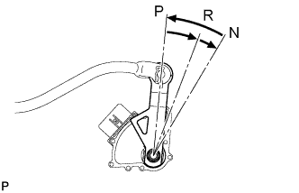
Turn the control shaft lever RH of the park/neutral position switch counterclockwise until it stops, and turn it clockwise 2 notches to set it to N.
-
Move the shift lever to N and tighten the nut while lightly pushing the shift lever toward R.
- Torque:
- 13 N*m { 130 kgf*cm, 9 ft.*lbf }
Note
Do not push the shift lever too hard.
-
Check that the shift lever moves smoothly and the shift lever and gear operate correctly.
-
-
CONNECT CABLE TO NEGATIVE BATTERY TERMINAL
Note
When disconnecting the cable, some systems need to be initialized after the cable is reconnected Click here.
-
ADD AUTOMATIC TRANSMISSION FLUID
-
INSPECT SHIFT LEVER POSITION
-
When moving the shift lever from P to R with the engine switch on (IG) and the brake pedal depressed, make sure that it moves smoothly and correctly into position.
-
Start the engine and make sure that the vehicle moves forward when the shift lever is in D and moves in reverse when the shift lever is in R. If the operation cannot be performed as specified, inspect the park/neutral position switch assembly and check the shift lever assembly installation condition.
-
-
CHECK RESET MEMORY