PARK / NEUTRAL POSITION SWITCH INSTALLATION

-
INSTALL PARK/NEUTRAL POSITION SWITCH ASSEMBLY
Tech Tips
Make sure that the manual valve lever shaft has not been rotated prior to installing the park/neutral position switch as the detent spring may become detached from the manual valve lever shaft.
-
Install the switch to the manual valve shaft.
-
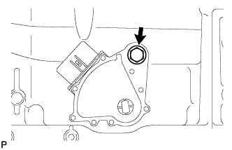
Temporarily install the bolt.
-
Install a new lock washer with the nut.
- Torque:
- 6.9 N*m { 70 kgf*cm, 61 in.*lbf }
-
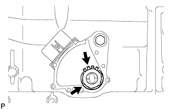
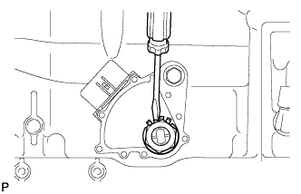
Temporarily install the control shaft lever.
-
Turn the control shaft lever counterclockwise until it stops, and then turn it clockwise 2 notches to set it to the N position.
-
Remove the control shaft lever.
-
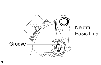
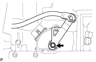
Align the groove with the neutral basic line.
-
Hold the switch in this position and tighten the bolt.
- Torque:
- 13 N*m { 133 kgf*cm, 10 ft.*lbf }
-
Using a screwdriver, bend the tabs of the lock washer.
Tech Tips
Bend at least 2 washer tabs.
-
Install the transmission control shaft lever with the spring washer and nut.
- Torque:
- 16 N*m { 163 kgf*cm, 12 ft.*lbf }
-
Connect the switch connector.
-
-
CONNECT FLOOR SHIFT GEAR SHIFTING ROD SUB-ASSEMBLY
-
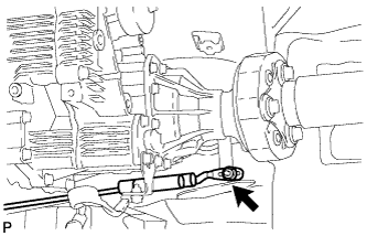
Temporarily connect the shifting rod to the connecting rod swivel with the nut.
Tech Tips
The nut will be tightened to a torque specification during the shift lever position adjustment procedure.
-
-
ADJUST SHIFT LEVER POSITION
-
Remove the nut and disconnect the shifting rod.
-
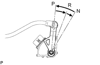
Turn the control shaft lever RH of the park/neutral position switch counterclockwise until it stops, and turn it clockwise 2 notches to set it to N.
-
Move the shift lever to N and tighten the nut while lightly pushing the shift lever toward R.
- Torque:
- 13 N*m { 130 kgf*cm, 9 ft.*lbf }
Note
Do not push the shift lever too hard.
-
Check that the shift lever moves smoothly and the shift lever and gear operate correctly.
-
-
INSTALL FRONT FLOOR NO. 1 HEAT INSULATOR
-
for 2WD:
Install the heat insulator with the 4 nuts.
- Torque:
- 5.4 N*m { 55 kgf*cm, 48 in.*lbf }
-
for AWD:
Install the heat insulator with the 6 nuts.
- Torque:
- 5.4 N*m { 55 kgf*cm, 48 in.*lbf }
-
-
INSTALL FRONT EXHAUST PIPE ASSEMBLY
-
Install the front exhaust pipe Click here.
-
-
CONNECT CABLE TO NEGATIVE BATTERY TERMINAL
Note
When disconnecting the cable, some systems need to be initialized after the cable is reconnected Click here.
-
INSTALL COWL TOP VENTILATOR LOUVER
-

for LHD:
Install the 6 clips and cowl top ventilator louver RH.
Note
If the cowl top ventilator louver RH is not properly installed, water may leak into the engine room and cause malfunctions. Therefore, make sure the cowl top ventilator louver RH is installed properly.
-

for RHD:
Install the 6 clips and cowl top ventilator louver LH.
Note
If the cowl top ventilator louver LH is not properly installed, water may leak into the engine room and cause malfunctions. Therefore, make sure the cowl top ventilator louver LH is installed properly.
-
-
INSPECT PARK/NEUTRAL POSITION SWITCH ASSEMBLY
-
Inspect the switch Click here.
-