GENERATOR INSTALLATION

-
INSTALL GENERATOR ASSEMBLY
-
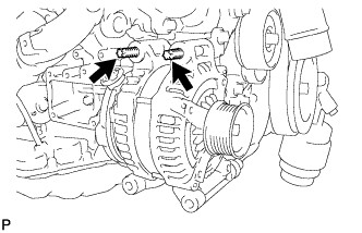
Using an E8 "TORX" socket wrench, set the generator with the 2 stud bolts.
- Torque:
- 10 N*m { 102 kgf*cm, 7 ft.*lbf }
-
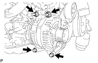
Install the generator with the 2 bolts and 2 nuts.
- Torque:
- 43 N*m { 438 kgf*cm, 32 ft.*lbf }
-
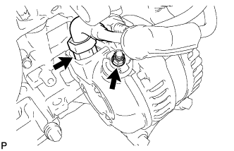
Connect the generator connector.
-
Connect the harness to the +B terminal with the nut.
- Torque:
- 12 N*m { 122 kgf*cm, 9 ft.*lbf }
-
-
INSTALL V-RIBBED BELT
-
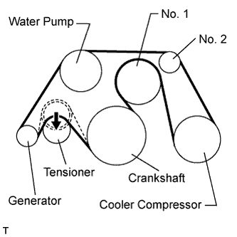
Install the V-ribbed belt as shown in the illustration.
Note
Check that the V-ribbed belt is properly set to each pulley.
-
Rotate the tensioner pulley counterclockwise, and then remove the fix bar.
-
-
-
INSTALL INTAKE AIR CONNECTOR PIPE
-
Install the intake air sound creator.
Tech Tips
Only perform this procedure when replacement of the intake air sound creator is necessary.
-
Install the intake air sound creator with the bolt and hose clamp.
- Torque:
- 2.0 N*m { 20 kgf*cm, 18 in.*lbf }
-
-
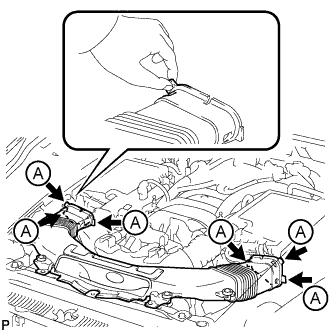
Align the protrusion of the intake air resonator with the cutout of the bracket and insert the protrusion.
-
Install the intake air connector pipe with the 3 hose clamps.
- Torque:
- for intake air connector pipe and throttle body
- 4.8 N*m { 49 kgf*cm, 42 in.*lbf }
- for intake air connector pipe and air cleaner cap
- 3.8 N*m { 39 kgf*cm, 34 in.*lbf }
Tech Tips
-
Insert the protrusion of the intake air connector pipe into the hole of the hose clamp.
-
The intake air connector pipe and throttle body clamp can be tightened within the range of 4.0 N*m (41 kgf*cm, 35 in.*lbf) to 5.5 N*m (56 kgf*cm, 49 in.*lbf), and the intake air connector pipe and air cleaner cap clamp can be tightened within the range of 2.0 N*m (20 kgf*cm, 18 in.*lbf) to 5.5 N*m (56 kgf*cm, 49 in.*lbf).
-
Attach the 2 wire harness clamps.
-
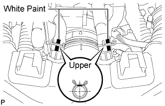
Connect the No. 1 and No. 2 ventilation hoses to the intake air connector pipe.
Tech Tips
-
Position the claws of the clamps as shown in the illustration.
-
Install the clamps so that they are within the hose's paint marks.
-
-
-
INSTALL NO. 2 ENGINE UNDER COVER (for 2WD)
-
Install the No. 2 engine under cover with the 8 bolts.
- Torque:
- for bolt A
- 10 N*m { 102 kgf*cm, 7 ft.*lbf }
- for bolt B
- 27 N*m { 275 kgf*cm, 20 ft.*lbf }
-
-
INSTALL NO. 2 ENGINE UNDER COVER (for AWD)
-
Install the No. 2 engine under cover with the 4 screws and 2 clips.
-
-
INSTALL FRONT SUSPENSION MEMBER PROTECTOR LOWER (for 2WD)
-
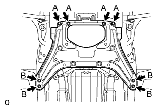
Install the front suspension member protector lower with the 8 bolts.
- Torque:
- 5.5 N*m { 56 kgf*cm, 49 in.*lbf }
-
-
INSTALL FRONT SUSPENSION MEMBER PROTECTOR LOWER (for AWD)
-
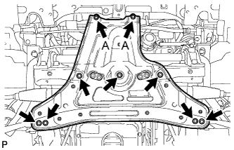
Install the front suspension member protector lower with the 9 bolts.
- Torque:
- for bolt A
- 20 N*m { 204 kgf*cm, 15 ft.*lbf }
- except bolt A
- 58 N*m { 593 kgf*cm, 43 ft.*lbf }
-
-
INSTALL NO. 1 ENGINE UNDER COVER
-
Install the No. 1 engine under cover with the 13 screws and 7 clips.
-
-
INSTALL FRONT WHEEL OPENING EXTENSION PAD LH (for AWD)
-
for 2WD:
Install the front wheel opening extension pad LH with the 2 screws.
-
for AWD:
Install the front wheel opening extension pad LH with the 5 screws.
-
-
INSTALL FRONT WHEEL OPENING EXTENSION PAD RH (for AWD)
Tech Tips
Use the same procedure described for the LH side.
-
INSTALL NO. 1 AIR CLEANER INLET
-
Align the holes with the connection areas labeled A, and attach the No. 1 air cleaner inlet.
-
Install the No. 1 air cleaner inlet with the 2 bolts.
- Torque:
- 5.0 N*m { 51 kgf*cm, 44 in.*lbf }
-
-
INSTALL AIR CLEANER INLET COVER SUB-ASSEMBLY
-
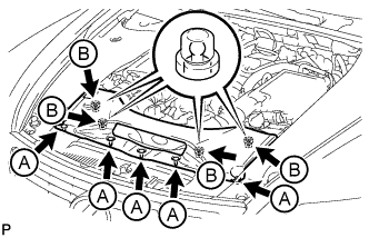
Attach the 4 clips labeled B.
Note
-
Make sure the clips are attached securely.
-
Attaching the clips forcefully or hitting the top of the clips may damage them.
-
-
Install the air cleaner inlet cover sub-assembly with the 5 clips labeled A.
-
-
INSTALL V-BANK COVER SUB-ASSEMBLY
-
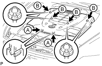
Slide the cover from the vehicle front toward the rear of the vehicle to attach the 2 clips labeled A, and then attach the 4 clips labeled B to install the V bank cover sub-assembly.
Note
-
Make sure the clips are attached securely.
-
Attaching the clips forcefully or hitting the top of the clips may damage them.
-
When attaching the clips labeled A, be sure to slide the cover from the front of the vehicle toward the rear of the vehicle.
-
-
-
CONNECT CABLE TO NEGATIVE BATTERY TERMINAL
Note
When disconnecting the cable, some systems need to be initialized after the cable is reconnected Click here.
-
INSTALL COWL TOP VENTILATOR LOUVER
-

for LHD:
Install the 6 clips and cowl top ventilator louver RH.
Note
If the cowl top ventilator louver RH is not properly installed, water may leak into the engine room and cause malfunctions. Therefore, make sure the cowl top ventilator louver RH is installed properly.
-

for RHD:
Install the 6 clips and cowl top ventilator louver LH.
Note
If the cowl top ventilator louver LH is not properly installed, water may leak into the engine room and cause malfunctions. Therefore, make sure the cowl top ventilator louver LH is installed properly.
-