STARTER INSTALLATION

-
INSTALL FLYWHEEL HOUSING SIDE COVER
-
INSTALL STARTER ASSEMBLY
-
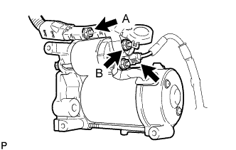
Connect the starter connector.
-
Connect the starter wire with the 2 nuts.
- Torque:
- for nut A
- 10 N*m { 102 kgf*cm, 7 ft.*lbf }
- for nut B
- 9.8 N*m { 100 kgf*cm, 87 in.*lbf }
-
Close the terminal cap.
-
Install the starter assembly with the 2 bolts.
- Torque:
- 37 N*m { 377 kgf*cm, 27 ft.*lbf }
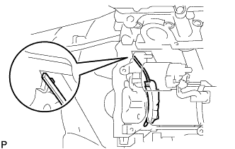
Note
Make sure the flywheel housing side cover is as shown in the illustration.
-
-
INSTALL NO. 3 EXHAUST MANIFOLD HEAT INSULATOR
-
Install the No. 3 exhaust manifold heat insulator with the 3 bolts.
- Torque:
- 10 N*m { 102 kgf*cm, 7 ft.*lbf }
-
-
INSTALL EXHAUST MANIFOLD SUB-ASSEMBLY RH
-
CONNECT CABLE TO NEGATIVE BATTERY TERMINAL
Note
When disconnecting the cable, some systems need to be initialized after the cable is reconnected Click here.
-
INSTALL COWL TOP VENTILATOR LOUVER RH
-

Install the 6 clips and cowl top ventilator louver RH.
Note
If the cowl top ventilator louver RH is not properly installed, water may leak into the engine room and cause malfunctions. Therefore, make sure the cowl top ventilator louver RH is installed properly.
-