INTAKE MANIFOLD INSTALLATION

-
INSTALL INTAKE MANIFOLD
-
Install 2 new gasket to the intake manifold.
-
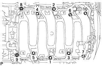
Temporarily install the intake manifold with the 2 nuts and 8 bolts. Then tighten the 2 nuts and 8 bolts uniformly in the order shown in the illustration.
- Torque:
- 21 N*m { 214 kgf*cm, 15 ft.*lbf }
-
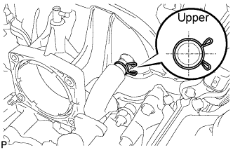
Connect the No. 1 ventilation hose to the intake manifold.
Note
Make sure that the clip is facing as shown in the illustration.
-
-
INSTALL VACUUM SWITCHING VALVE ASSEMBLY
-
Install the vacuum switching valve assembly with the bolt.
- Torque:
- 21 N*m { 214 kgf*cm, 15 ft.*lbf }
-
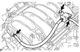
Connect the fuel vapor feed hose to the intake manifold.
-
Connect the No. 2 fuel vapor feed hose to the vacuum switching valve assembly.
-
-
INSTALL WATER BY-PASS PIPE SUB-ASSEMBLY
-
Install the water by-pass pipe sub-assembly to the intake manifold with the 2 bolts.
- Torque:
- 10 N*m { 102 kgf*cm, 7 ft.*lbf }
-
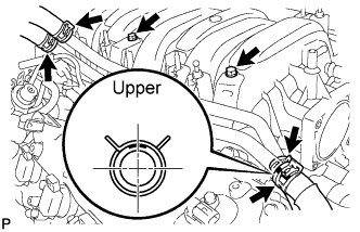
Connect the heater water inlet hose, heater water outlet hose, water inlet hose, and No. 3 water by-pass hose to the water by-pass pipe sub-assembly with the 4 clamps.
Note
Make sure that the No. 3 water by-pass hose clip is facing as shown in the illustration.
-
-
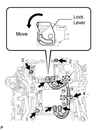
INSTALL INJECTOR DRIVER
-
Install the injector driver to the intake manifold by installing the 2 bolts and 2 nuts in the order shown in the illustration.
- Torque:
- 10 N*m { 102 kgf*cm, 7 ft.*lbf }
-
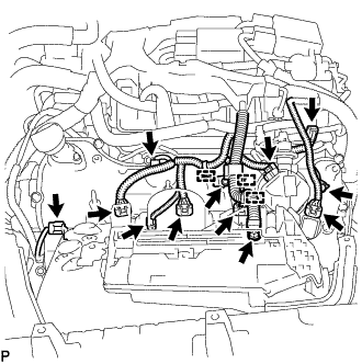
Connect the 4 wire harness connectors to the injector driver. Then move the lock lever as shown in the illustration to lock the connectors.
-
Connect the 2 clamps to the injector driver.
-
-
CONNECT ENGINE WIRE (for LHD)
-
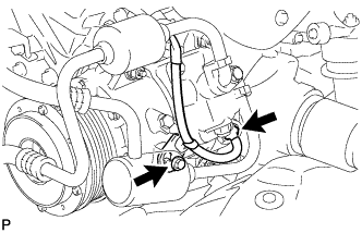
Connect the cooler compressor connector.
-
Connect the wire harness bracket with the bolt.
- Torque:
- 10 N*m { 102 kgf*cm, 7 ft.*lbf }
-
Install the clamp bracket with the bolt.
- Torque:
- 10 N*m { 102 kgf*cm, 7 ft.*lbf }
-
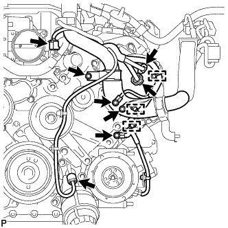
Connect the 3 clamps and 3 ground wires with the 3 bolts.
- Torque:
- 10 N*m { 102 kgf*cm, 7 ft.*lbf }
-
Connect the 2 camshaft timing control motor connectors (for Bank 1).
-
Connect the oil pressure sensor connector.
-
Connect the engine coolant temperature sensor connector.
-
Connect the clamp and install the 2 clamp brackets with the 2 bolts.
- Torque:
- 10 N*m { 102 kgf*cm, 7 ft.*lbf }
-
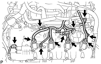
Connect the No. 8 engine wire connector.
-
Connect the fuel pump connector (for high pressure).
-
Connect the 2 VVT sensor connectors.
-
Connect the 4 ignition coil connectors.
-
Connect the camshaft timing control valve connector.
-
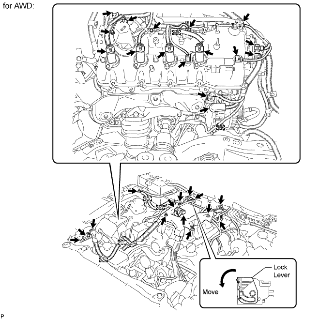
for AWD:
-
Connect the engine wire harness with the 4 nuts.
- Torque:
- 10 N*m { 102 kgf*cm, 7 ft.*lbf }
-
Install the 2 engine wire harness clamp brackets with the 2 bolts.
- Torque:
- 10 N*m { 102 kgf*cm, 7 ft.*lbf }
-
Connect the engine wire to the fusible link block assembly with the nut.
- Torque:
- 13 N*m { 127 kgf*cm, 10 ft.*lbf }
-
Connect the engine wire harness to the +B terminal of the generator assembly with the nut.
- Torque:
- 12 N*m { 122 kgf*cm, 9 ft.*lbf }
-
Connect the 6 engine wire harness clamps.
-
Connect the engine wire harness connectors.
Tech Tips
To connect the injector driver connectors, move the lock lever to lock the connector.
-
-
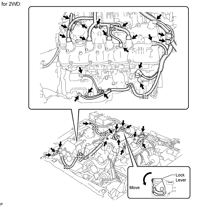
for 2WD:
-
Connect the engine wire harness with the 4 nuts.
- Torque:
- 10 N*m { 102 kgf*cm, 7 ft.*lbf }
-
Install the 3 engine wire harness clamp brackets with the 3 bolts.
- Torque:
- 10 N*m { 102 kgf*cm, 7 ft.*lbf }
-
Connect the engine wire to the fusible link block assembly with the nut.
- Torque:
- 13 N*m { 127 kgf*cm, 9 ft.*lbf }
-
Connect the engine wire harness to the +B terminal of the generator assembly with the nut.
- Torque:
- 12 N*m { 122 kgf*cm, 9 ft.*lbf }
-
Connect the 7 engine wire harness clamps.
-
Connect the engine wire harness connectors.
Tech Tips
To connect the injector driver connectors, move the lock lever to lock the connector.
-
-
-
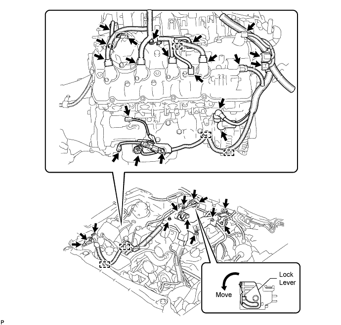
CONNECT ENGINE WIRE (for RHD)
-
Connect the cooler compressor connector.
-
Connect the wire harness bracket with the bolt.
- Torque:
- 10 N*m { 102 kgf*cm, 7 ft.*lbf }
-
Install the clamp bracket with the bolt.
- Torque:
- 10 N*m { 102 kgf*cm, 7 ft.*lbf }
-
Connect the 3 clamps and 3 ground wires with the 3 bolts.
- Torque:
- 10 N*m { 102 kgf*cm, 7 ft.*lbf }
-
Connect the 2 camshaft timing control motor connectors (for Bank 1).
-
Connect the oil pressure sensor connector.
-
Connect the engine coolant temperature sensor connector.
-
Connect the engine wire to the fusible link block assembly with the nut.
- Torque:
- 13 N*m { 127 kgf*cm, 9 ft.*lbf }
-
Attach the 3 wire harness clamps.
-
Connect the clamp and install the 2 clamp brackets with the 2 bolts.
- Torque:
- 10 N*m { 102 kgf*cm, 7 ft.*lbf }
-
Connect the No. 8 engine wire connector.
-
Connect the fuel pump connector (for high pressure).
-
Connect the 2 VVT sensor connectors.
-
Connect the 4 ignition coil connectors.
-
Connect the camshaft timing control valve connector.
-
Connect the engine wire harness with the 4 nuts.
- Torque:
- 10 N*m { 102 kgf*cm, 7 ft.*lbf }
-
Install the 3 engine wire harness clamp brackets with the 3 bolts.
- Torque:
- 10 N*m { 102 kgf*cm, 7 ft.*lbf }
-
Connect the 5 engine wire harness clamps.
-
Connect the engine wire harness to the +B terminal of the generator assembly with the nut.
- Torque:
- 12 N*m { 122 kgf*cm, 9 ft.*lbf }
-
Connect the engine wire harness connectors.
Tech Tips
To connect the injector driver connectors, move the lock lever to lock the connector.
-
-
INSTALL NO. 6 ENGINE COVER SUB-ASSEMBLY (for AWD)
-
Install the No. 6 engine cover sub-assembly with the 2 nuts.
- Torque:
- 15 N*m { 153 kgf*cm, 11 ft.*lbf }
-
-
INSTALL NO. 5 ENGINE COVER SUB-ASSEMBLY (for AWD)
-
Install the No. 5 engine cover sub-assembly with the 2 nuts.
- Torque:
- 15 N*m { 153 kgf*cm, 11 ft.*lbf }
-
-
INSTALL NO. 2 ENGINE COVER (for LHD with 2WD)
-
Install the No. 2 engine cover with the 4 nuts.
- Torque:
- 21 N*m { 214 kgf*cm, 15 ft.*lbf }
-
-
INSTALL AIR CLEANER ASSEMBLY LH
-
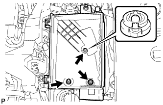
Install the air cleaner case LH with the 2 nuts and clip.
- Torque:
- 5.0 N*m { 51 kgf*cm, 44 in.*lbf }
-
Install the air cleaner filter element to the air cleaner case LH.
-
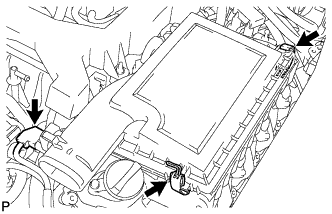
Install the air cleaner cap LH with the 2 clamps.
-
Connect the mass air flow meter connector.
-
-
INSTALL AIR CLEANER ASSEMBLY RH
-
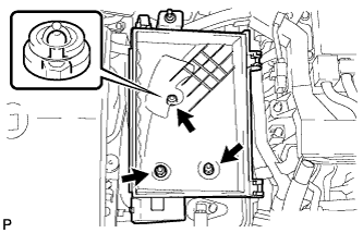
Install the air cleaner case RH with the 2 nuts and clip.
- Torque:
- 5.0 N*m { 51 kgf*cm, 44 in.*lbf }
-
Install the air cleaner filter element to the air cleaner case RH.
-
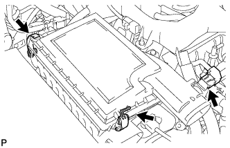
Install the air cleaner cap RH with the 2 clamps.
-
Connect the mass air flow meter connector.
-
-
INSTALL FRONT SUSPENSION MEMBER PROTECTOR LOWER
-
for 2WD: Click here
-
for AWD: Click here
-
-
INSTALL NO. 2 ENGINE UNDER COVER
-
for 2WD: Click here
-
for AWD: Click here
-
-
INSTALL THROTTLE BODY
-
CONNECT CABLE TO NEGATIVE BATTERY TERMINAL
Note
When disconnecting the cable, some systems need to be initialized after the cable is reconnected Click here.
-
INSTALL ENGINE ROOM SIDE COVER RH
-
Install the engine room side cover RH with the 5 clips.
-
-
INSTALL ENGINE ROOM SIDE COVER LH
-
Install the engine room side cover LH with the 5 clips.
-
-
INSTALL COWL TOP VENTILATOR LOUVER
-

for LHD:
Install the 6 clips and cowl top ventilator louver RH.
Note
If the cowl top ventilator louver RH is not properly installed, water may leak into the engine room and cause malfunctions. Therefore, make sure the cowl top ventilator louver RH is installed properly.
-

for RHD:
Install the 6 clips and cowl top ventilator louver LH.
Note
If the cowl top ventilator louver LH is not properly installed, water may leak into the engine room and cause malfunctions. Therefore, make sure the cowl top ventilator louver LH is installed properly.
-