INTAKE MANIFOLD REMOVAL

-
PRECAUTION
Note
After turning the engine switch off, waiting time may be required before disconnecting the cable from the battery terminal. Therefore, make sure to read the disconnecting the cable from the battery terminal notice before proceeding with work Click here.
-
REMOVE COWL TOP VENTILATOR LOUVER
-

for LHD:
Remove the 6 clips and cowl top ventilator louver RH.
-

for RHD:
Remove the 6 clips and cowl top ventilator louver LH.
-
-
DISCONNECT CABLE FROM NEGATIVE BATTERY TERMINAL
Note
When disconnecting the cable, some systems need to be initialized after the cable is reconnected Click here.
-
REMOVE ENGINE ROOM SIDE COVER LH
-
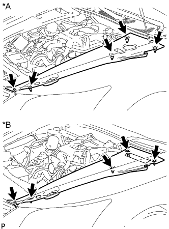
Text in Illustration *A for LHD *B for RHD Remove the 5 clips and engine room side cover LH.
-
-
REMOVE ENGINE ROOM SIDE COVER RH
-
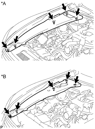
Text in Illustration *A for LHD *B for RHD Remove the 5 clips and engine room side cover RH.
-
-
REMOVE THROTTLE BODY
-
REMOVE NO. 2 ENGINE UNDER COVER
-
for 2WD: Click here
-
for AWD: Click here
-
-
REMOVE FRONT SUSPENSION MEMBER PROTECTOR LOWER
-
for 2WD: Click here
-
for AWD: Click here
-
-
REMOVE AIR CLEANER ASSEMBLY LH
-
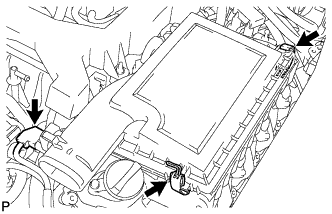
Disconnect the mass air flow meter connector.
-
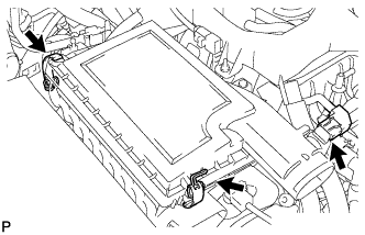
Disconnect the 2 clamps and remove the air cleaner cap LH.
-
Remove the air cleaner filter element from air cleaner case LH.
-
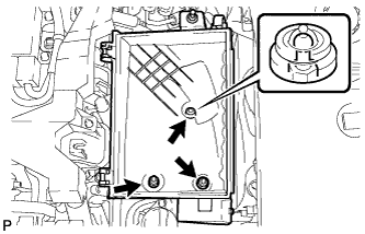
Remove the 2 nuts, clip and air cleaner case LH.
-
-
REMOVE AIR CLEANER ASSEMBLY RH
-
Disconnect the mass air flow meter connector.
-
Disconnect the 2 clamps and remove the air cleaner cap RH.
-
Remove the air cleaner filter element from air cleaner case RH.
-
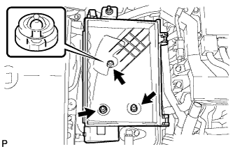
Remove the 2 nuts, clip and air cleaner case RH.
-
-
REMOVE NO. 2 ENGINE COVER (for LHD with 2WD)
-
Remove the 4 nuts and No. 2 engine cover.
-
-
REMOVE NO. 5 ENGINE COVER SUB-ASSEMBLY (for AWD)
-
Remove the 2 nuts and No. 5 engine cover sub-assembly.
-
-
REMOVE NO. 6 ENGINE COVER SUB-ASSEMBLY (for AWD)
-
Remove the 2 nuts and No. 6 engine cover sub-assembly.
-
-
DISCONNECT ENGINE WIRE (for LHD)
Tech Tips
Fix the disconnected harnesses, etc. in place with tape or equivalent so that they do not interfere.
-
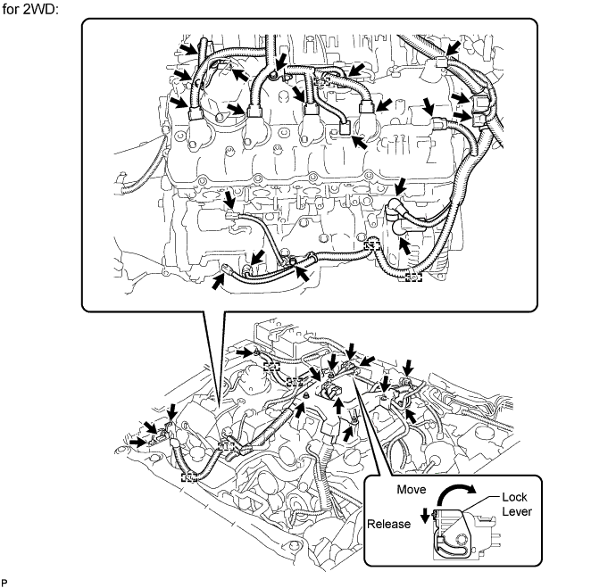
for 2WD:
-
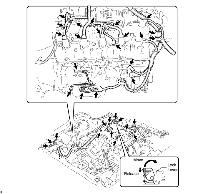
Disconnect the engine wire harness connectors.
Tech Tips
To disconnect the injector driver connectors, push the claw downward and move the lock lever to release the lock.
-
Remove the nut and disconnect the engine wire harness from the +B terminal of the generator assembly.
-
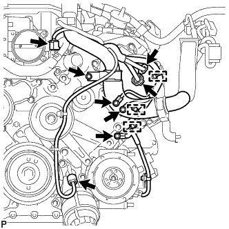
Using a clip remover, disconnect the 7 engine wire harness clamps.
-
Remove the nut and disconnect the engine wire from the fusible link block assembly.
-
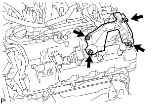
Remove the 3 bolts and 3 engine wire harness clamp brackets.
-
Remove the 4 nuts and disconnect the engine wire harness.
-
-
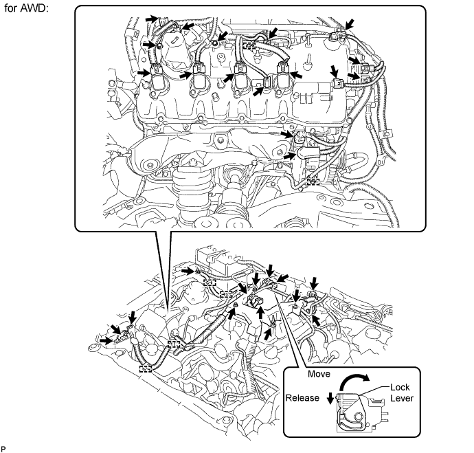
for AWD:
-
Disconnect the engine wire harness connectors.
Tech Tips
To disconnect the injector driver connectors, push the claw downward and move the lock lever to release the lock.
-
Remove the nut and disconnect the engine wire harness from the +B terminal of the generator assembly.
-
Using a clip remover, disconnect the 4 engine wire harness clamps.
-
Remove the 2 bolts and 2 engine wire harness clamp brackets.
-
Remove the 4 nuts and disconnect the engine wire harness.
-
-
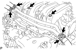
Disconnect the camshaft timing control valve connector.
-
Disconnect the 4 ignition coil connectors.
-
Disconnect the 2 VVT sensor connectors.
-
Disconnect the fuel pump connector (for high pressure).
-
Disconnect the No. 8 engine wire connector.
-
Remove the 2 bolts and disconnect the clamp and 2 clamp brackets.
-
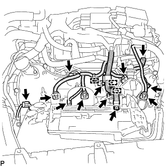
Disconnect the engine coolant temperature sensor connector.
-
Disconnect the oil pressure sensor connector.
-
Disconnect the 2 camshaft timing control motor connectors (for Bank 1).
-
Remove the 3 bolts and disconnect the 3 clamps and 3 ground wires.
-
Remove the bolt and clamp bracket.
-
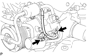
Remove the bolt and disconnect the wire harness bracket.
-
Disconnect the cooler compressor connector.
-
-
DISCONNECT ENGINE WIRE (for RHD)
Tech Tips
Fix the disconnected harnesses, etc. in place with tape or equivalent so that they do not interfere.
-
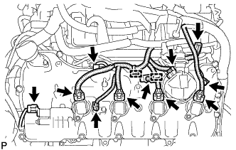
Disconnect the engine wire harness connectors.
Tech Tips
To disconnect the injector driver connectors, push the claw downward and move the lock lever to release the lock.
-
Remove the nut and disconnect the engine wire harness from the +B terminal of the generator assembly.
-
Using a clip remover, disconnect the 5 engine wire harness clamps.
-
Remove the 3 bolts and 3 engine wire harness clamp brackets.
-
Remove the 4 nuts and disconnect the engine wire harness.
-
Disconnect the camshaft timing control valve connector.
-
Disconnect the 4 ignition coil connectors.
-
Disconnect the 2 VVT sensor connectors.
-
Disconnect the fuel pump connector (for high pressure).
-
Disconnect the No. 8 engine wire connector.
-
Remove the 2 bolts and 2 clamp brackets.
-
Using a clip remover, detach the 3 engine harness clamps.
-
Remove the nut and disconnect the engine wire from the fusible link block assembly.
-
Disconnect the engine coolant temperature sensor connector.
-
Disconnect the oil pressure sensor connector.
-
Disconnect the 2 camshaft timing control motor connectors (for Bank 1).
-
Remove the 3 bolts and disconnect the 3 clamps and 3 ground wires.
-
Remove the bolt and clamp bracket.
-
Remove the bolt and disconnect the wire harness bracket.
-
Disconnect the cooler compressor connector.
-
-
REMOVE INJECTOR DRIVER
-
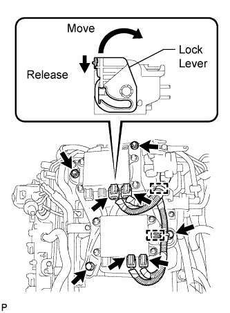
Disconnect the 4 injector driver connectors.
Tech Tips
To disconnect the injector driver connectors, push the claw downward and move the lock lever to release the lock.
-
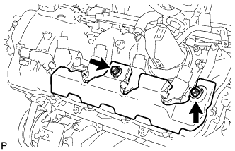
Disconnect the 2 clamps from the injector driver.
-
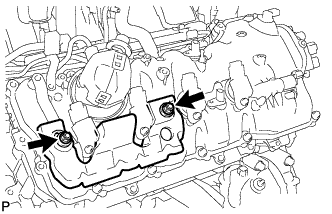
Remove the 2 bolts, 2 nuts and injector driver from the intake manifold.
-
-
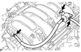
REMOVE WATER BY-PASS PIPE SUB-ASSEMBLY
-
Slide the 4 clamps and disconnect the heater water inlet hose, heater water outlet hose, water inlet hose, and No. 3 water by-pass hose from the water by-pass pipe sub-assembly.
-
Remove the 2 bolts and water by-pass pipe sub-assembly.
-
-
REMOVE VACUUM SWITCHING VALVE ASSEMBLY
-
Disconnect the fuel vapor feed hose and No. 2 fuel vapor feed hose.
-
Remove the bolt and vacuum switching valve assembly.
-
-
REMOVE INTAKE MANIFOLD
-
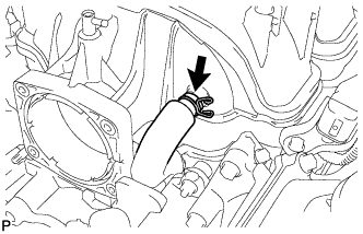
Disconnect the No. 1 ventilation hose from the intake manifold.
-
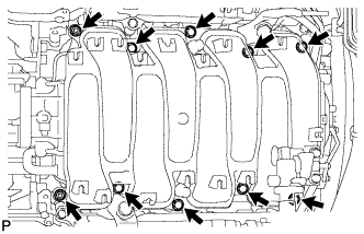
Remove the 8 bolts, 2 nuts and intake manifold.
-
Remove the 2 gaskets from the intake manifold.
-