EXHAUST MANIFOLD (for 2WD) REMOVAL

-
REMOVE COWL TOP VENTILATOR LOUVER
-

for LHD:
Remove the 6 clips and cowl top ventilator louver RH.
-

for RHD:
Remove the 6 clips and cowl top ventilator louver LH.
-
-
PRECAUTION
Note
After turning the engine switch off, waiting time may be required before disconnecting the cable from the battery terminal. Therefore, make sure to read the disconnecting the cable from the battery terminal notice before proceeding with work Click here.
-
DISCONNECT CABLE FROM NEGATIVE BATTERY TERMINAL
Note
When disconnecting the cable, some systems need to be initialized after the cable is reconnected Click here.
-
REMOVE FRONT EXHAUST PIPE ASSEMBLY
-
REMOVE FRONT SUSPENSION MEMBER REINFORCEMENT LH
-
REMOVE FRONT SUSPENSION MEMBER REINFORCEMENT RH
Tech Tips
Use the same procedure described for the LH side.
-
REMOVE V-BANK COVER SUB-ASSEMBLY
-
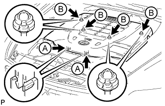
Using both hands, lift the rear side of the cover upwards to detach the 4 clips labeled B. Then slide the cover toward the front of the vehicle to detach the 2 clips labeled A and remove the V-bank cover sub-assembly.
Note
-
The V-bank cover sub-assembly may be damaged if its front and rear are lifted at the same time.
-
When detaching the clips labeled A, be sure to slide the cover toward the front of the vehicle.
-
-
-
REMOVE AIR CLEANER INLET COVER SUB-ASSEMBLY
-
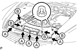
Remove the 5 clips labeled A.
-
Lift up the air cleaner inlet cover sub-assembly to detach the 4 clips labeled B, and remove the air cleaner inlet cover sub-assembly.
-
-
REMOVE NO. 1 AIR CLEANER INLET
-

Remove the 2 bolts.
-
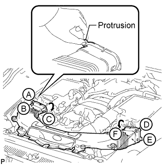
Hold the No. 1 air cleaner inlet by the protrusions labeled A and labeled B, and detach the connections.
-
Rotate the No. 1 air cleaner inlet as shown in the illustration to detach the protrusion labeled C.
-
Hold the No. 1 air cleaner inlet by the protrusions labeled D and labeled E, and detach the connections.
-
Rotate the No. 1 air cleaner inlet as shown in the illustration to detach the protrusion labeled F.
-
-
REMOVE INTAKE AIR CONNECTOR PIPE
-
Disconnect the No. 1 and No. 2 ventilation hoses from the intake air connector pipe.
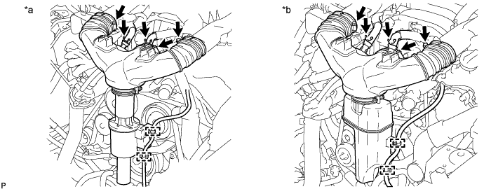
Text in Illustration *a w/ Intake Air Sound Creator *b w/ Intake Air Resonator -
Using a clip remover, detach the 2 wire harness clamps.
-
Loosen the 3 hose clamps, and remove the intake air connector pipe.
-
Remove the intake air sound creator.
Tech Tips
Only perform this procedure when replacement of the intake air sound creator is necessary.
-
Loosen the hose clamp and remove the intake air sound creator.
-
-
-
REMOVE V-RIBBED BELT
-

Rotate the tensioner pulley counterclockwise to loosen the belt tension.
Tech Tips
The pulley bolt for the belt tensioner has a left-handed thread.
-
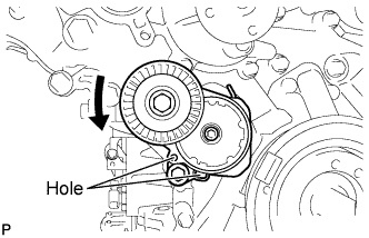
While turning the belt tensioner counterclockwise, align the holes. Insert a bar with a diameter of 5 mm (0.197 in.) into the holes to fix the belt tensioner in place.
-
-
Remove the V-ribbed belt.
-
-
REMOVE ENGINE ROOM SIDE COVER RH
-
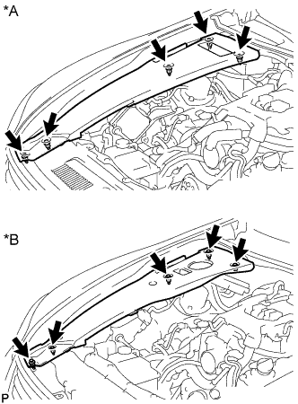
Text in Illustration *A for LHD *B for RHD Remove the 5 clips and engine room side cover RH.
-
-
REMOVE ENGINE ROOM SIDE COVER LH
-
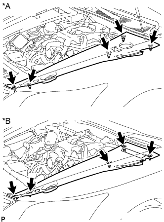
Text in Illustration *A for LHD *B for RHD Remove the 5 clips and engine room side cover LH.
-
-
REMOVE NO. 1 ENGINE UNDER COVER
-
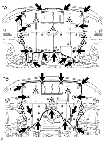
Text in Illustration *A for 2WD *B for AWD Remove the 13 screws, 7 clips and No. 1 engine under cover.
-
-
REMOVE FRONT SUSPENSION MEMBER PROTECTOR LOWER
-
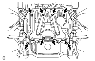
Remove the 8 bolts and front suspension member protector lower.
-
-
REMOVE NO. 1 EXHAUST PIPE SUPPORT BRACKET SUB-ASSEMBLY
-
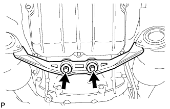
Remove the 2 bolts and No. 1 exhaust pipe support bracket sub-assembly.
-
-
REMOVE GENERATOR ASSEMBLY
-
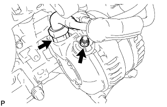
Remove the nut, and disconnect the harness from the +B terminal.
-
Disconnect the generator connector.
-
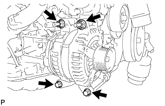
Remove the 2 bolts and 2 nuts.
-
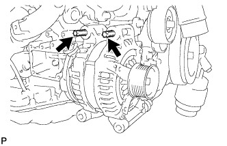
Using an E8 "TORX" socket wrench, remove the 2 stud bolts and generator.
-
-
REMOVE STEERING SLIDING YOKE WITH SHAFT SUB-ASSEMBLY (w/ VGRS)
-
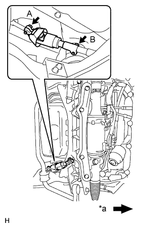
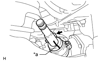
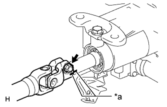
Text in Illustration *a Front of the vehicle Loosen bolt A and remove bolt B, then slide the steering sliding with shaft yoke.
Note
-
Do not remove bolt A.
-
Do not separate the steering sliding with shaft yoke from the power steering link.
-
-
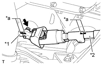
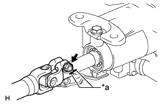
Text in Illustration *1 No. 2 steering intermediate shaft *2 Power steering link *a Matchmark Put matchmarks on the steering sliding with shaft yoke, No. 2 steering intermediate shaft and power steering link.
-
Remove the bolt and the steering sliding with shaft yoke from the power steering link.
-
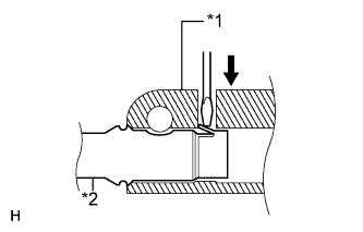
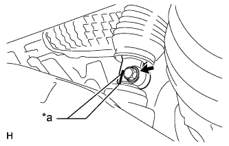
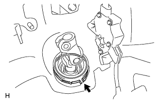
Text in Illustration *1 Steering sliding with shaft yoke *2 No. 2 steering intermediate shaft Separate the steering sliding with shaft yoke from the No. 2 steering intermediate shaft.
Tech Tips
Insert a screwdriver or equivalent into the yoke's hole. Hold down the intermediate shaft's claw and remove the No. 2 steering intermediate shaft. If the claw is damaged, remove the claw. The intermediate shaft does not have to be replaced.
-
-
REMOVE STEERING SLIDING YOKE WITH SHAFT SUB-ASSEMBLY (w/o VGRS)
-
Text in Illustration *a Front of the Vehicle Loosen bolt A and remove bolt B, then slide the steering sliding with shaft yoke.
Note
-
Do not remove bolt A.
-
Do not separate the steering sliding with shaft yoke from the intermediate shaft.
-
-
Text in Illustration *1 No. 2 steering intermediate shaft *2 Intermediate shaft *a Matchmark Put matchmarks on the steering sliding with shaft yoke, No. 2 steering intermediate shaft and intermediate shaft.
-
Remove the bolt and the steering sliding with shaft yoke from the steering intermediate shaft.
-
Text in Illustration *1 Steering sliding with shaft yoke *2 No. 2 steering intermediate shaft Separate the steering sliding with shaft yoke from the No. 2 steering intermediate shaft.
Tech Tips
Insert a screwdriver or equivalent into the yoke's hole. Hold down the intermediate shaft's claw and remove the intermediate shaft. If the claw is damaged, remove the claw. The intermediate shaft does not have to be replaced.
-
-
REMOVE STEERING INTERMEDIATE SHAFT (w/o VGRS)
-
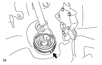
Text in Illustration *a Matchmark Put matchmarks on the steering intermediate shaft and power steering link.
-
Remove the bolt and steering intermediate shaft.
-
-
REMOVE NO. 2 STEERING INTERMEDIATE SHAFT ASSEMBLY (w/ VGRS)
-
Text in Illustration *a Matchmark Put matchmarks on the No. 2 steering intermediate shaft and steering column.
-
Remove the bolt.
-
Text in Illustration *a Matchmark Put matchmarks on the No. 2 steering intermediate shaft and power steering link.
-
Remove the bolt.
-
Remove the clamp and No. 2 steering intermediate shaft.
-
-
REMOVE NO. 2 STEERING INTERMEDIATE SHAFT ASSEMBLY (w/o VGRS)
-
Text in Illustration *a Matchmark Put matchmarks on the No. 2 steering intermediate shaft and the steering column.
-
Remove the bolt.
-
Remove the clamp and No. 2 steering intermediate shaft.
-
-
REMOVE ENGINE OIL LEVEL DIPSTICK GUIDE
-
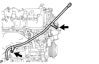
Remove the engine oil level dipstick.
-
Remove the 2 bolts and engine oil level dipstick guide.
-
-
REMOVE NO. 1 EXHAUST MANIFOLD HEAT INSULATOR
-
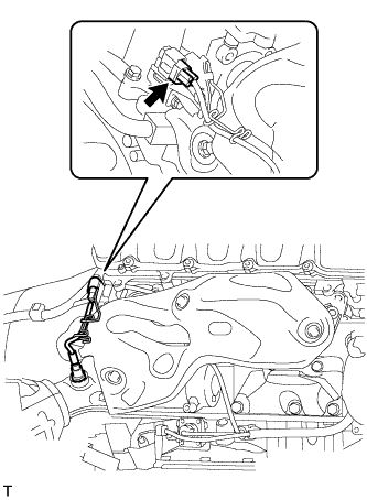
Disconnect the air fuel ratio sensor connector.
-
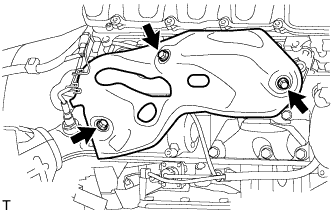
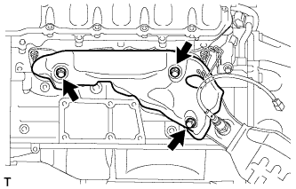
Remove the 3 bolts and No. 1 exhaust manifold heat insulator.
-
-
REMOVE EXHAUST MANIFOLD SUB-ASSEMBLY RH
-
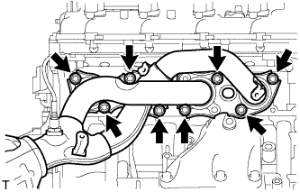
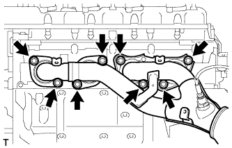
Remove the 8 nuts and exhaust manifold RH.
-
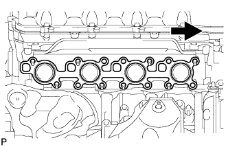
Remove the gasket.
Text in Illustration 
Front
-
-
REMOVE NO. 2 EXHAUST MANIFOLD HEAT INSULATOR
-
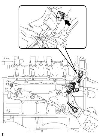
Disconnect the air fuel ratio sensor connector.
-
Remove the 3 bolts and No. 2 exhaust manifold heat insulator.
-
-
REMOVE EXHAUST MANIFOLD SUB-ASSEMBLY LH
-
Remove the 8 nuts and exhaust manifold LH.
-
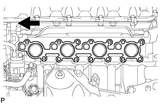
Remove the gasket.
Text in Illustration Front
-
-
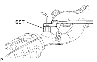
REMOVE AIR FUEL RATIO SENSOR (for Bank 1 Sensor 1)
-
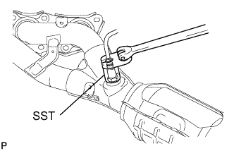
Using SST, remove the air fuel ratio sensor from the exhaust manifold LH.
- SST
- 09224-00010
-
-
REMOVE AIR FUEL RATIO SENSOR (for Bank 2 Sensor 1)
-
Using SST, remove the air fuel ratio sensor from the exhaust manifold RH.
- SST
- 09224-00010
-