EXHAUST PIPE INSTALLATION

CAUTION:
Perform the procedures below with at least 2 people.
-
INSTALL NO. 1 EXHAUST PIPE SUPPORT BRACKET SUB-ASSEMBLY
-
Install the No. 1 exhaust pipe support bracket sub-assembly with the 2 bolts.
- Torque:
- 43 N*m { 438 kgf*cm, 32 ft.*lbf }
-
-
INSTALL EXHAUST PIPE DAMPER
-
Install the exhaust pipe damper to the tailpipe LH with 2 new bolts.
- Torque:
- 19 N*m { 194 kgf*cm, 14 ft.*lbf }
Note
Do not reuse the 2 removed bolts.
-
Install the exhaust pipe damper to the tailpipe LH with 2 new bolts.
- Torque:
- 19 N*m { 194 kgf*cm, 14 ft.*lbf }
Note
Do not reuse the 2 removed bolts.
-
-
INSTALL TAILPIPE RH
-
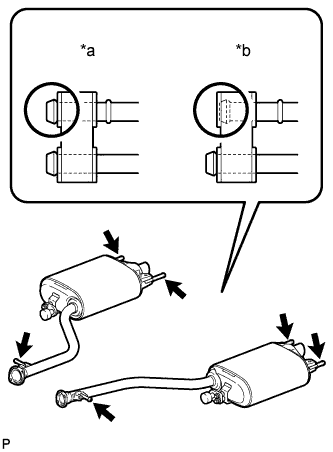
Text in Illustration *a CORRECT *b INCORRECT Connect the 3 exhaust pipe supports to install the tailpipe RH.
-
-
INSTALL TAILPIPE LH
-
Connect the 3 exhaust pipe supports to install the tailpipe LH.
-
-
INSTALL FRONT EXHAUST PIPE ASSEMBLY
-
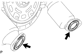
Install 2 new gaskets to the exhaust manifold LH and exhaust manifold RH.
Note
Do not reuse the 2 removed gaskets.
-
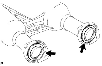
Install 2 new gaskets to the front exhaust pipe rear ends.
Note
Do not reuse the 2 removed gaskets.
-
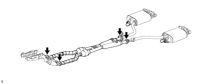
Install the front exhaust pipe assembly with the 4 bolts and 4 new nuts.
- Torque:
- 39 N*m { 398 kgf*cm, 29 ft.*lbf }
Note
Do not reuse the 4 removed nuts.
Tech Tips
-
During installation, hold the front exhaust pipe assembly.
-
Hold the bolt and then tighten the nut with the specified torque.
-
Install the front exhaust pipe assembly to the tailpipe LH and tailpipe RH with the 4 bolts.
- Torque:
- 39 N*m { 398 kgf*cm, 29 ft.*lbf }
Tech Tips
During installation, hold the front exhaust pipe assembly.
-
-
INSTALL FRONT CENTER FLOOR BRACE SUB-ASSEMBLY
-
Push in the 2 clips in the upward direction of the vehicle and install the front center floor brace sub-assembly with the 8 bolts.
- Torque:
- 7.4 N*m { 75 kgf*cm, 65 in.*lbf }
-
-
CONNECT HEATED OXYGEN SENSOR (for Sensor 2)
Note
Do not strike the metal part of the heated oxygen sensor.
-
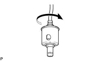
Pre-rotate the heated oxygen sensor 4 times counterclockwise, and then connect the sensor to the front exhaust pipe assembly by hand.
-
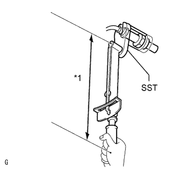
Text in Illustration *1 Fulcrum Length Using SST, tighten the 2 heated oxygen sensors.
- SST
- 09224-00010
- Torque:
- without SST
- 44 N*m { 449 kgf*cm, 32 ft.*lbf }
- with SST
- 40 N*m { 408 kgf*cm, 30 ft.*lbf }
Tech Tips
-
Use a torque wrench with a fulcrum length of 300 mm (11.8 in.). When using a torque wrench with a fulcrum length that is not 300 mm (11.8 in.), calculate the torque specification for the torque wrench and SST based on the "without SST" torque specification Click here.
-
Make sure SST and the torque wrench are connected in a straight line.
-
Connect the 2 grommets to the floor panel.
-
-
INSPECT FOR EXHAUST GAS LEAK
-
If gas is leaking, tighten the areas necessary to stop the leak. Replace the damaged parts as necessary.
-
-
INSTALL FRONT FLOOR COVER RH
-
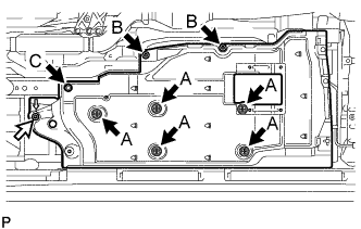
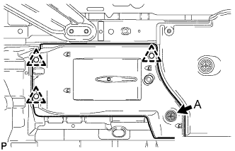
Push in the 5 clips labeled A in the illustration in the upward direction of the vehicle to install the front floor cover RH.
Text in Illustration 
Clip 
Nut -
Tighten the 2 clips labeled B in the illustration.
-
Install the clip labeled C and the nut.
- Torque:
- 5.4 N*m { 55 kgf*cm, 48 in.*lbf }
-
Install the front floor service hole cover with the 4 clips.
-
-
INSTALL FRONT FLOOR COVER LH
-
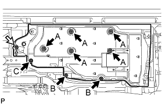
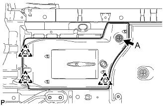
Push in the 5 clips labeled A in the illustration in the upward direction of the vehicle to install the front floor cover LH.
Text in Illustration Clip Nut -
Tighten the 2 clips labeled B in the illustration.
-
Install the clip labeled C and the nut.
- Torque:
- 5.4 N*m { 55 kgf*cm, 48 in.*lbf }
-
Install the front floor service hole cover with the 4 clips.
-
-
INSTALL FRONT FENDER MAIN SEAL RH
-
Push in the clip labeled A in the illustration in the upward direction of the vehicle and install the front fender main seal RH with the 3 clips.
-
-
INSTALL FRONT FENDER MAIN SEAL LH
-
Push in the clip labeled A in the illustration in the upward direction of the vehicle and install the front fender main seal LH with the 3 clips.
-
-
INSTALL REAR FLOOR SIDE MEMBER COVER RH
-
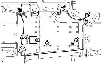
Install the rear floor side member cover RH with the 3 clips, 2 screws, nut and bolt.
- Torque:
- 5.4 N*m { 55 kgf*cm, 48 in.*lbf }
Text in Illustration Bolt Nut 
Screw
-
-
INSTALL REAR FLOOR SIDE MEMBER COVER LH
-
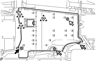
Install the rear floor side member cover LH with the 3 clips, 2 screws, nut and bolt.
- Torque:
- 5.4 N*m { 55 kgf*cm, 48 in.*lbf }
Text in Illustration Bolt Nut Screw
-
-
INSTALL NO. 5 ROCKER PANEL MOULDING PROTECTOR
-
Install the No. 5 rocker panel moulding protector with the 2 clips and screw.
-
-
INSTALL NO. 6 ROCKER PANEL MOULDING PROTECTOR
-
Install the No. 6 rocker panel moulding protector with the 2 clips and screw.
-
-
INSTALL NO. 1 DIFFERENTIAL SUPPORT PROTECTOR
Tech Tips
Use the same procedure described for the No. 2 differential support protector.
-
INSTALL NO. 2 DIFFERENTIAL SUPPORT PROTECTOR
-
Install the differential support protector with the 3 nuts.
- Torque:
- 5.4 N*m { 55 kgf*cm, 48 in.*lbf }
-