ENGINE (for AWD) ON-VEHICLE INSPECTION

-
CHECK V-RIBBED BELT
-
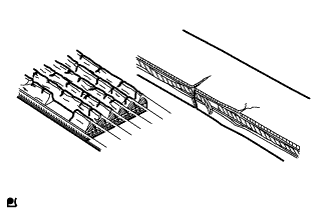
Check the belt for wear, cracks or other signs of damage.
If any of the following defects is found, replace the V-ribbed belt.
Tech Tips
-
The belt is cracked.
-
The belt is worn out to the extent that the cords are exposed.
-
The belt has chunks missing from the ribs.
-
-
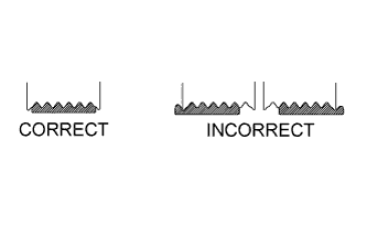
Check that the belt fits properly in the ribbed grooves.
Tech Tips
Check with your hand to confirm that the belt has not slipped out of the groove on the bottom of the pulley. If it has slipped out, replace the V-ribbed belt. Install a new V-ribbed belt correctly.
-
-
INSPECT V-RIBBED BELT TENSIONER ASSEMBLY
-
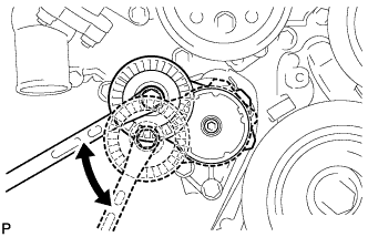
Check that nothing gets caught in the tensioner by turning it clockwise and counterclockwise.
If a malfunction exists, replace the V-ribbed belt tensioner assembly.
-
-
INSPECT VALVE LASH ADJUSTER NOISE
-
Rev up the engine several times. Check that the engine does not emit unusual noises.
If unusual noises occur, warm up the engine and idle it for over 30 minutes. Then perform the inspection above again.
If any defects or problems are found during the inspection above, perform a lash adjuster inspection Click here.
-
-
INSPECT IGNITION TIMING
-
Warm up and stop the engine.
Tech Tips
A warmed up engine should have an engine coolant temperature of over 80°C (176°F) and an engine oil temperature of 60°C (140°F), and the engine rpm should be stabilized.
-
When using the Intelligent tester:
-
Connect the Intelligent tester to the DLC3.
-
Start the engine and idle it.
-
Turn the tester on.
-
Enter the following menus: Powertrain / Engine and ECT / Data List / Primary / IGN Advance.
Tech Tips
Refer to the Intelligent tester operator's manual for further details.
Standard Ignition Timing 8 to 18° BTDC @ idle
-
-
When not using the Intelligent tester:
-
Remove the V-bank cover.
-
Remove the 5 clips and air cleaner inlet cover.
-
Remove the 5 clips and engine room side cover LH.
-
Remove the 2 bolts and No. 1 air cleaner inlet.
-
Disconnect the air cleaner cap LH.
-
Remove the 2 nuts and air cleaner case LH.
-
Connect the tester probe of a timing light to the wire of the ignition connector for No. 1 cylinder.
Note
Use a timing light that detects primary signals.
-
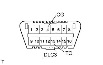
Using SST, connect terminals 13 (TC) and 4 (CG) of the DLC3.
- SST
- 09843-18040
Note
-
Confirm the terminal numbers before connecting them. Connecting the wrong terminals can damage the engine.
-
When checking the ignition timing, the transmission should be in neutral.
-
Using a timing light, check the ignition timing.
Standard Ignition Timing 8 to 12° BTDC @ idle -
Remove SST from the DLC3.
-
Check the ignition timing.
Standard Ignition Timing 8 to 18° BTDC @ idle -
Check that the ignition timing advances immediately when the engine speed is increased.
-
Disconnect the timing light from the engine.
-
Install the air cleaner case LH with the 2 nuts.
- Torque:
- 5.0 N*m { 51 kgf*cm, 44 in.*lbf }
-
Connect the air cleaner cap LH.
-
Install the No. 1 air cleaner inlet with the 2 bolts.
- Torque:
- 5.0 N*m { 51 kgf*cm, 44 in.*lbf }
-
Install the engine room side cover LH with the 5 clips.
-
Install the air cleaner inlet cover with the 5 clips.
-
Install the V-bank cover.
-
-
-
INSPECT ENGINE IDLE SPEED
-
Warm up and stop the engine.
Tech Tips
A warmed up engine should have an engine coolant temperature of over 80°C (176°F) and an engine oil temperature of 60°C (140°F), and the engine rpm should be stabilized.
-
When using the Intelligent tester:
-
Connect the Intelligent tester to the DLC3.
Note
Switch off all accessories and the A/C before connecting the Intelligent tester.
-
Race the engine at 2500 rpm for approximately 90 seconds.
-
Turn the tester on.
-
Enter the following menus: Powertrain / Engine and ECT / Data List / Primary / Engine Speed.
Standard Idle Speed 700 to 800 rpm Note
When checking the idle speed, the transmission should be in neutral.
Tech Tips
Refer to the Intelligent tester operator's manual for further details.
If the idle speed is not as specified, check the air intake system.
-
Disconnect the Intelligent tester from the DLC3.
-
-
When not using the Intelligent tester:
-
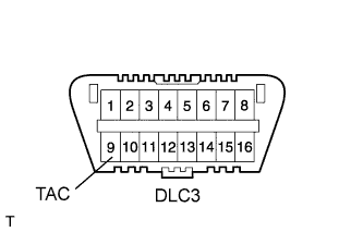
Using SST, connect a tachometer probe to terminal 9 (TAC) of the DLC3.
- SST
- 09843-18030
Note
Confirm the terminal numbers before connecting them. Connecting the wrong terminals can damage the engine.
-
Race the engine at 2500 rpm for approximately 90 seconds.
-
Check the idle speed.
Idle Speed (Transmission Neutral Position) 700 to 800 rpm If the speed is not as specified, check the air intake system.
-
Disconnect the tachometer from the DLC3.
-
-
-
INSPECT COMPRESSION
Note
After turning the engine switch off, waiting time may be required before disconnecting the cable from the battery terminal. Therefore, make sure to read the disconnecting the cable from the battery terminal notice before proceeding with work Click here.
-
Warm up and stop the engine.
Tech Tips
A warmed up engine should have an engine coolant temperature of over 80°C (176°F) and an engine oil temperature of 60°C (140°F), and the engine rpm should be stabilized.
-
Remove the V-bank cover.
-
Remove the 5 clips and air cleaner inlet cover.
-
Remove the 5 clips and engine room side cover LH.
-
Remove the 5 clips and engine room side cover RH.
-
Remove the 2 bolts and No. 1 air cleaner inlet.
-
Remove the 4 nuts and 2 air cleaner assemblies.
-
Disconnect the cable from the negative (-) battery terminal.
Note
When disconnecting the cable, some systems need to be initialized after the cable is reconnected Click here.
-
Remove the battery and tray.
-
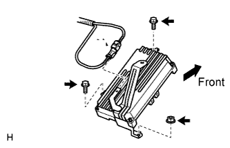
Remove the 2 bolts, nut and skid control ECU.
-
Remove the bolt, 2 nuts and skid control ECU bracket.
-
Remove the bolt and engine oil level dipstick guide.
-
Remove the 2 nuts and No. 5 engine cover.
-
Remove the 2 nuts and No. 6 engine cover.
-
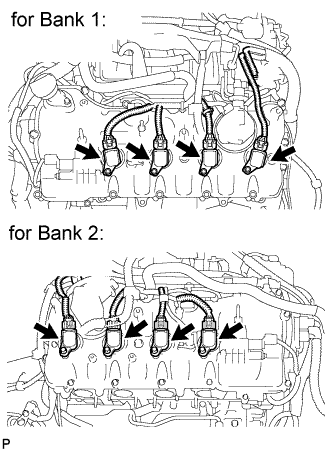
Disconnect the 8 ignition coil connectors.
-
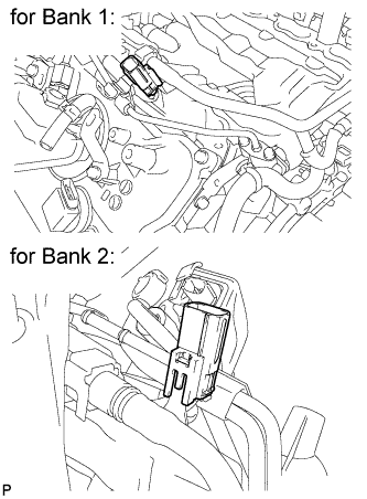
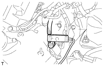
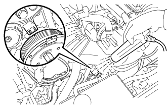
Disconnect the 2 injector connectors as shown in the illustration.
-
Remove the 8 bolts and 8 ignition coils.
-
Remove the 8 spark plugs.
-
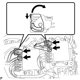
Disconnect the 4 injector driver connectors as shown in the illustration.
-
Cylinder under the battery installation position:
Inspect the compression pressure.
-
Insert a compression gauge into the spark plug hole.
-
Install the battery and tray.
-
Connect the cable to the negative (-) battery terminal.
Note
When disconnecting the cable, some systems need to be initialized after the cable is reconnected Click here.
-
Depress and hold the brake pedal, and turn the engine switch on (IG). Then check the compression pressure.
Note
The measurement must be done as quickly as possible.
Tech Tips
Always use a fully charged battery to obtain engine speed of 200 rpm or more.
Standard Compression Pressure 1400 kPa (14.3 kgf/cm2, 203 psi) or more Minimum Pressure 1000 kPa (10.2 kgf/cm2, 145 psi) -
Turn the engine switch off.
-
Disconnect the cable from the negative (-) battery terminal.
Note
When disconnecting the cable, some systems need to be initialized after the cable is reconnected Click here.
-
Remove the battery and tray.
-
Remove the compression gauge.
-
-
Cylinder other than cylinder under the battery installation position:
Inspect the compression pressure.
-
Insert a compression gauge into the spark plug hole.
-
Install the battery and tray.
-
Connect the cable to the negative (-) battery terminal.
Note
When disconnecting the cable, some systems need to be initialized after the cable is reconnected Click here.
-
Depress and hold the brake pedal, and turn the engine switch on (IG). Then check the compression pressure.
Note
The measurement must be done as quickly as possible.
Tech Tips
Always use a fully charged battery to obtain engine speed of 200 rpm or more.
Standard Compression Pressure 1400 kPa (14.3 kgf/cm2, 203 psi) or more Minimum Pressure 1000 kPa (10.2 kgf/cm2, 145 psi) -
Remove the compression gauge.
-
Perform the inspection above for each cylinder.
-
Check the pressure difference between each compression pressure.
Pressure Difference 100 kPa (1.0 kgf/cm2, 14.5 psi) or less -
If the cylinder compression is low in one or more cylinders, pour a small amount of engine oil into the cylinder with low compression through its spark plug hole. Then inspect the cylinder compression pressure again.
Tech Tips
-
If adding oil helps boost the compression, it is likely that the piston rings and/or cylinder bore are worn or damaged.
-
If pressure stays low, a valve may be stuck or seated improperly, or there may be leakage in the gasket.
-
-
Disconnect the cable from the negative (-) battery terminal.
Note
When disconnecting the cable, some systems need to be initialized after the cable is reconnected Click here.
-
Remove the battery and tray.
-
-
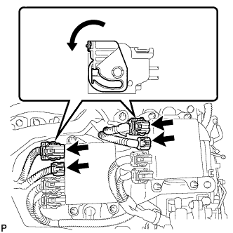
Connect the 4 injector driver connectors as shown in the illustration.
-
Install the 8 spark plugs.
-
Install the 8 ignition coils with the 8 bolts.
-
Connect the 8 ignition coil connectors.
-
Connect the 2 injector connectors.
-
Install the No. 6 engine cover with the 2 nuts.
-
Install the No. 5 engine cover with the 2 nuts.
-
Install the engine oil level dipstick guide with the bolt.
-
Install the skid control ECU bracket with the bolt and 2 nuts.
- Torque:
- 8.5 N*m { 87 kgf*cm, 75 in.*lbf }
-
Install the skid control ECU with the 2 bolts and nut.
- Torque:
- 8.5 N*m { 87 kgf*cm, 75 in.*lbf }
-
Install the battery and tray.
-
Connect the cable to the negative (-) battery terminal.
Note
When disconnecting the cable, some systems need to be initialized after the cable is reconnected Click here.
-
Install the 2 air cleaner assemblies with the 4 nuts.
-
Install the No. 1 air cleaner inlet with the 2 bolts.
-
Install the engine room side cover RH with the 5 clips.
-
Install the engine room side cover LH with the 5 clips.
-
Install the air cleaner inlet cover with the 5 clips.
-
Install the V-bank cover.
-
Clear the DTCs Click here.
-
-
INSPECT CO/HC
Tech Tips
This check determines whether or not the idle CO/HC complies with regulations.
-
Start the engine.
-
Keep the engine speed at 2500 rpm for approximately 180 seconds.
-
Insert the CO/HC meter testing probe at least 40 cm (1.31 ft.) into the tailpipe during idling.
-
Immediately check CO/HC concentration at idle and 2500 rpm.
Tech Tips
-
When performing the 2 mode (2500 rpm and idle) test, follow the measurement order prescribed by the applicable local regulations.
-
If the CO/HC concentration does not comply with regulations, troubleshoot in the order given below.
-
Check the air fuel ratio sensor Click here and heated oxygen sensor Click here operation.
-
See the table below for possible causes, and then inspect and correct the applicable causes if necessary.
CO HC Symptom Causes Normal High Rough idle
-
Faulty ignitions
-
Incorrect timing
-
Plugs (contaminated, shorted, or gaps are defective)
-
Leaky intake and exhaust valves
-
Leaky cylinder
Low High Rough idle
(Fluctuating HC reading)
-
Vacuum leaks
-
PCV hose
-
Intake manifold
-
Throttle body
-
Lean mixture causing misfire
High High Rough idle
(Black smoke from exhaust)
-
Restricted air filter
-
Faulty SFI system
-
Faulty pressure
-
Defective engine coolant temperature sensor
-
Faulty ECM
-
Faulty injector
-
Faulty throttle position sensor
-
Faulty mass air flow meter
-
-
-