KNOCK SENSOR INSTALLATION

-
INSTALL KNOCK SENSOR
-
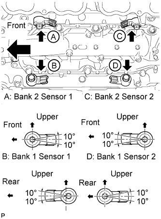
Install the 4 knock sensors with the 4 bolts so that the sensors are angled as shown in the illustration.
- Torque:
- 20 N*m { 204 kgf*cm, 15 ft.*lbf }
Tech Tips
The acceptable installation angle of the sensors is between 10° upwards and downwards from the horizontal position.
-
Connect the 4 knock sensor connectors.
-
-
INSTALL SEPARATOR CASE
-
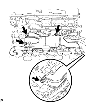
Install the separator case with the 4 bolts.
- Torque:
- 10 N*m { 102 kgf*cm, 7 ft.*lbf }
-
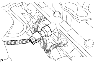
Connect the fuel pressure sensor connector.
-
-
INSTALL NO. 4 FUEL PIPE SUB-ASSEMBLY
-
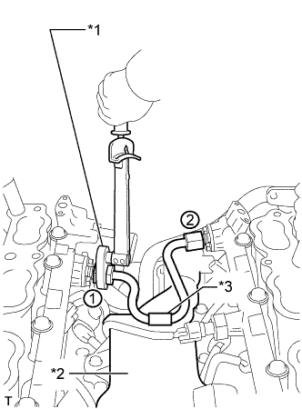
Text in Illustration *1 Union Nut Wrench *2 Separator Case *3 Fuel Pipe Protector Temporarily install the No. 4 fuel pipe sub-assembly.
-
Using a 19 mm union nut wrench, tighten the No. 4 fuel pipe sub-assembly in the order shown in the illustration.
- Torque:
- 30 N*m { 306 kgf*cm, 22 ft.*lbf }
Note
-
After installing the No. 4 fuel pipe sub-assembly, check that the fuel pipe protector contacts with the separator case.
-
Use the formula to calculate special torque values for situations where a union nut wrench is combined with a torque wrench Click here.
-
-
INSTALL NO. 2 ENGINE COVER SUB-ASSEMBLY LH
-
INSTALL NO. 2 ENGINE COVER SUB-ASSEMBLY
-
INSTALL NO. 1 ENGINE COVER SUB-ASSEMBLY
-
INSTALL INTAKE MANIFOLD
-
INSPECT FOR FUEL LEAK