CAMSHAFT OIL CONTROL VALVE INSTALLATION

-
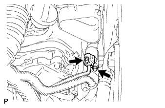
INSTALL CAMSHAFT TIMING OIL CONTROL VALVE ASSEMBLY (for Bank 1)
-
Apply a light coat of engine oil to a new O-ring, and install it to the camshaft timing oil control valve assembly.
-
Install the camshaft timing oil control valve assembly with the bolt.
- Torque:
- 10 N*m { 102 kgf*cm, 7 ft.*lbf }
Note
-
Do not allow foreign matter to contact the oil seal face of the camshaft timing oil control valve assembly (connecting surface with cylinder head cover sub-assembly).
-
Be careful that the O-ring is not cracked or jumped when installing the camshaft timing oil control valve assembly.
-
Connect the camshaft timing oil control valve assembly connector.
-
-
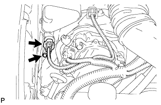
INSTALL CAMSHAFT TIMING OIL CONTROL VALVE ASSEMBLY (for Bank 2)
-
Apply a light coat of engine oil to a new O-ring, and install it to the camshaft timing oil control valve assembly.
-
Install the camshaft timing oil control valve assembly with the bolt.
- Torque:
- 10 N*m { 102 kgf*cm, 7 ft.*lbf }
Note
-
Do not allow foreign matter to contact the oil seal face of the camshaft timing oil control valve assembly (connecting surface with cylinder head cover sub-assembly).
-
Be careful that the O-ring is not cracked or jumped when installing the camshaft timing oil control valve assembly.
-
Connect the camshaft timing oil control valve assembly connector.
-
-
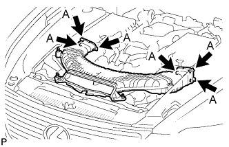
INSTALL NO. 1 AIR CLEANER INLET
-
Align the holes with the connection areas labeled A, and attach the No. 1 air cleaner inlet.
-

Install the No. 1 air cleaner inlet with the 2 bolts.
- Torque:
- 5.0 N*m { 51 kgf*cm, 44 in.*lbf }
-
-
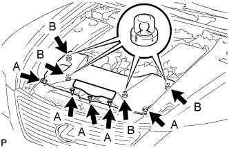
INSTALL AIR CLEANER INLET COVER
-
Attach the 4 clips B.
Note
-
Make sure the clips are attached securely.
-
Attaching the clips forcefully or hitting the top of the clips may damage them.
-
-
Install the air cleaner inlet cover sub-assembly with the 5 clips labeled A.
-
-
INSTALL V-BANK COVER SUB-ASSEMBLY
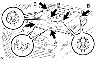
-
After sliding the cover from the vehicle front to the rear to attaching the 2 clips labeled A, attach the 4 clips labeled B and install the V-bank cover sub-assembly.
Note
-
Make sure the clips are attached securely.
-
Attaching the clips forcefully or hitting the top of the clips may damage them.
-
-
-
CONNECT CABLE TO NEGATIVE BATTERY TERMINAL
Note
When disconnecting the cable, some systems need to be initialized after the cable is reconnected Click here.
-
INSTALL COWL TOP VENTILATOR LOUVER RH
-

Install the 6 clips and cowl top ventilator louver RH.
Note
If the cowl top ventilator louver RH is not properly installed, water may leak into the engine room and cause malfunctions. Therefore, make sure the cowl top ventilator louver RH is installed properly.
-
-
DRIVING TEST
-
After the engine is warmed up, perform the driving test. Then check that the camshaft timing oil control valve assembly operates normally.
-