РЫЧАГ ПЕРЕКЛЮЧЕНИЯ ПЕРЕДАЧ УСТАНОВКА
-
INSTALL SHIFT LEVER ASSEMBLY
Note
Check that the park/neutral position switch and the shift lever are in N.
-
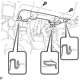
Install the shift lever assembly with the 4 bolts and 2 screws.
- Torque:
- Bolt
- 12 N*m { 122 kgf*cm, 9 ft.*lbf }
-
Connect the 2 connectors.
-
-
CONNECT TRANSMISSION CONTROL CABLE ASSEMBLY
-
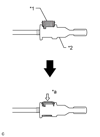
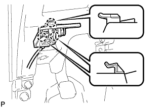
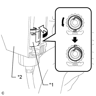
Turn the nut of the transmission control cable assembly 180° counterclockwise. While holding the nut in place, push in the stopper until the stopper clicks twice.
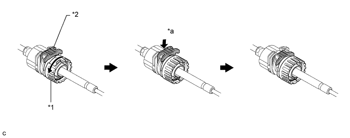
Text in Illustration *1 Nut *2 Stopper *a Push in - - -
Install the outer part of the transmission control cable assembly to the shift lever retainer. Check that the spring is positioned at "A" and push in the stopper.
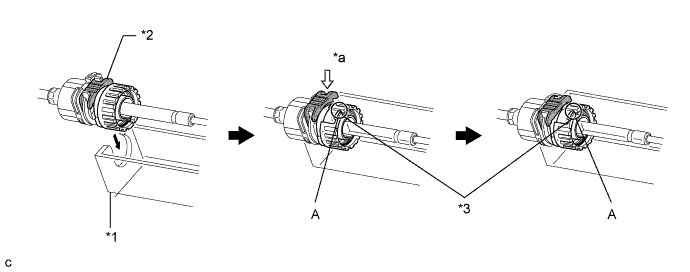
Text in Illustration *1 Shift Lever Retainer *2 Stopper *3 Spring - - *a Push in - - Tech Tips
If the stopper cannot be pushed in, slightly turn the nut clockwise and then push in the stopper again.
-
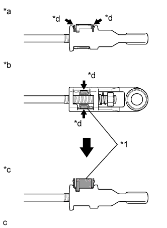
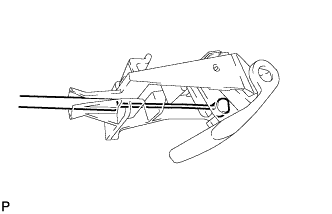
Text in Illustration *1 Lock Piece *a Side View *b Bottom View *c Side View *d Push Push the 2 claws together at the top of the transmission control cable assembly lock piece. While holding the 2 claws together, push the 2 lugs on the bottom of the lock piece toward each other and upward to pull out the lock piece.
-
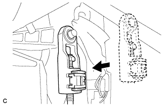
Install the cable end to the shift control unit.
Note
-
Check that the lock piece is pulled up.
-
Install the cable end all the way to the base of the pin.
-
-
Text in Illustration *1 Lock Piece *2 Adjuster Case *a Push in Push the lock piece into the adjuster case.
Note
Securely push in the lock piece until it locks.
-
-
INSTALL AIR CONDITIONING CONTROL ASSEMBLY
-
Подсоедините разъем.
-
Установите панель управления системы кондиционирования в сборе и введите в зацепление 4 захвата.
-
-
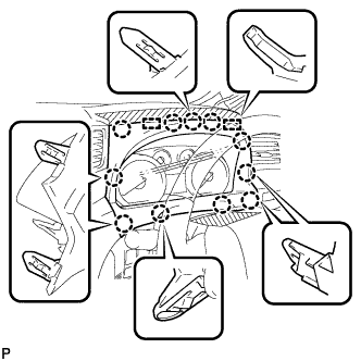
INSTALL NO. 3 INSTRUMENT CLUSTER FINISH PANEL GARNISH
-
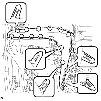
Установите облицовку панели управления № 3 и закрепите ее 16 захватами.
Note
Убедитесь, что захваты надежно зафиксированы.
-
-
INSTALL NO. 2 INSTRUMENT CLUSTER FINISH PANEL GARNISH
-
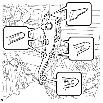
Установите облицовку панели управления № 2 и закрепите ее 8 захватами.
Note
Убедитесь, что захваты надежно зафиксированы.
-
-
INSTALL CENTER INSTRUMENT CLUSTER FINISH PANEL SUB-ASSEMBLY
-
Подсоедините разъем.
-
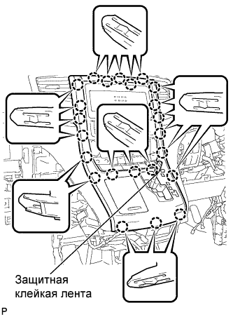
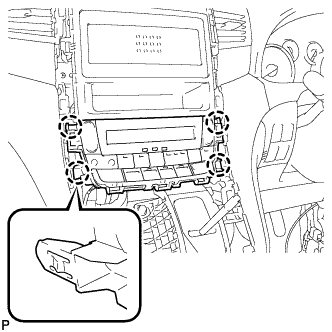
Установите центральную облицовку панели управления в сборе и закрепите ее 23 захватами.
Note
-
При установке центральной облицовки панели управления необходимо сильно нажимать на верхнюю среднюю часть.
-
Убедитесь, что захваты надежно зафиксированы.
-
-
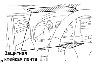
Удалите нанесенную защитную ленту.
-
Установите рычаг переключения передач в положение P.
-
-
INSTALL SHIFT LEVER KNOB SUB-ASSEMBLY
-
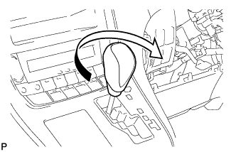
Поверните рукоятку рычага переключения передач по часовой стрелке и закрепите ее.
-
-
INSTALL INSTRUMENT CLUSTER FINISH PANEL ASSEMBLY
-
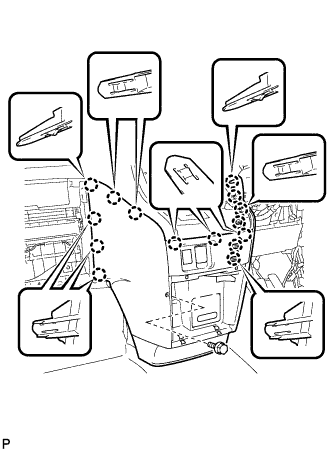
Введите в зацепление 15 захвата.
Tech Tips
Прежде чем ввести в зацепление 15 захватов, убедитесь, что они расположены правильно.
Note
Убедитесь, что захваты надежно зафиксированы.
-
Установите облицовку панели управления в сборе и закрепите ее болтом <C>.
-
-
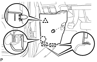
INSTALL INSTRUMENT PANEL BOX ASSEMBLY
-
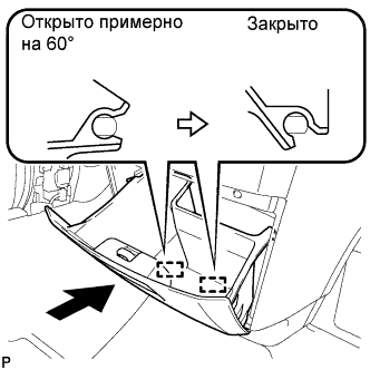
Открыв ящик панели приборов в сборе примерно на 60° по отношению к закрытому положению, введите в зацепление 2 петли по горизонтали.
Note
Посадка дверцы на петли сверху может привести к деформации петель. Будьте внимательны, устанавливайте ящик панели приборов строго горизонтально.
-
Установите амортизирующий фиксатор.
-
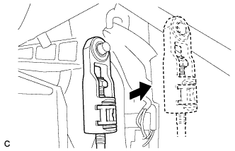
Слегка отогните упоры (A) и (B) в направлениях, указанных стрелками на рисунке, и введите их в зацепление, чтобы закрепить ящик панели приборов в сборе.
-
-
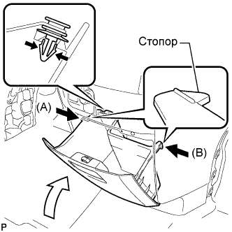
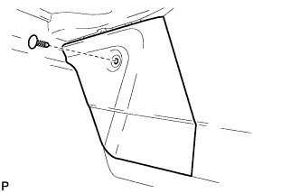
INSTALL GLOVE COMPARTMENT DOOR ASSEMBLY
-
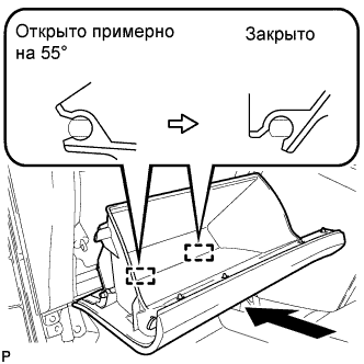
Открыв дверцу перчаточного ящика в сборе примерно на 55° по отношению к закрытому положению, введите в зацепление 2 петли по горизонтали.
Note
Посадка дверцы на петли сверху может привести к деформации петель. Будьте внимательны, устанавливайте дверцу отделения перчаточного ящика строго горизонтально.
-
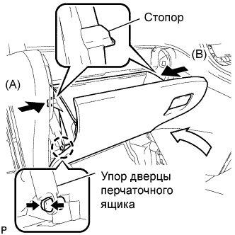
Слегка отогните упоры (A) и (B) в направлениях, указанных стрелками на рисунке, и введите их в зацепление, чтобы закрепить дверцу перчаточного ящика в сборе.
-
Установите упор дверцы перчаточного ящика и зацепите захват.
-
-
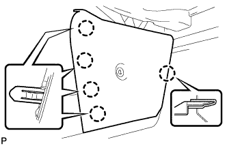
INSTALL CENTER FLOOR CARPET COVER LH
-
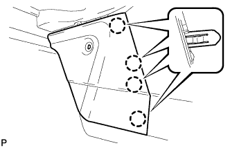
Введите в зацепление 4 захвата.
-
Установите левую центральную накладку напольного коврика и закрепите ее 1 фиксатором.
-
-
INSTALL CENTER FLOOR CARPET COVER RH
-
Введите в зацепление 5 захватов.
-
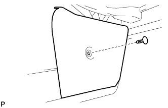
Установите правую центральную накладку напольного коврика и закрепите ее 1 фиксатором.
-
-
INSTALL LOWER INSTRUMENT PANEL FINISH PANEL
-

Введите в зацепление 3 направляющие, 13 захватов и фиксатор.
Tech Tips
Убедитесь, что все захваты по всей окружности подушки безопасности для защиты коленей водителя полностью вошли в зацепление.
Note
Убедитесь, что захваты надежно зафиксированы.
-
Установите нижнюю отделочную накладку панели приборов и закрепите ее 3 винтами <B>.
-
Подсоедините устройство блокировки крышки наливной горловины топливного бака к рычагу открывания устройства блокировки топливной крышки.
-
Введите в зацепление 3 захвата и снимите трос управления топливной крышкой.
-
Введите в зацепление 3 захвата и снимите трос управления замком капота.
-
-
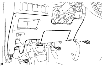
INSTALL NO. 1 INSTRUMENT PANEL UNDER COVER SUB-ASSEMBLY
-
Введите зажим в зацепление.
-
Подсоедините все разъемы.
-
Введите в зацепление 2 захвата и направляющую.
Note
Убедитесь, что захваты надежно зафиксированы.
-
Установите нижнюю крышку панели приборов № 1 и закрепите ее 2 винтами <B>.
-
-
INSTALL NO. 1 INSTRUMENT CLUSTER FINISH PANEL
-
Установите облицовку панели управления № 1, закрепив ее 11 захватами и 2 направляющими.
-
Снимите защитную ленту с кожуха рулевой колонки.
-
-
INSTALL COWL SIDE TRIM BOARD LH
-
Установите боковую облицовочную накладку с левой стороны кожуха и закрепите ее фиксатором, захватом и 2 направляющими.
-
Установите фиксатор (A).
-
-
CONNECT CABLE TO NEGATIVE BATTERY TERMINAL
Note
When disconnecting the cable, some systems need to be initialized after the cable is reconnected Click here.
-
INSPECT SHIFT LEVER POSITION
-
When moving the shift lever from P to R with the engine switch on (IG) and the brake pedal depressed, make sure that the shift lever moves smoothly and correctly into position.
-
Start the engine and make sure that the vehicle moves forward when moving the shift lever from N to D and moves rearward when moving the lever to R.
If the operation cannot be performed as specified, inspect the park/neutral position switch assembly and check the shift lever assembly installation condition.
-
-
ADJUST SHIFT LEVER POSITION
-
Apply the parking brake and move the shift lever to N.
-
Remove the instrument cluster finish panel assembly and center instrument cluster finish panel sub-assembly Click here.
-
Disconnect the end of the transmission control cable assembly from the shift lever assembly.
-
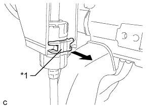
Text in Illustration: *1 Stopper Pull out the stopper of the transmission control cable.
Note
Do not remove the stopper. If the stopper is removed, reinstall it to its original position.
-
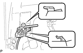
Text in Illustration *1 Nut *2 Shift Lever Retainer Rotate the nut counterclockwise approximately 180° and, while holding the nut in that position, disconnect the transmission control cable assembly from the shift lever retainer.
Note
Do not over-rotate the nut as it will come off the internal spring and the transmission control cable assembly will not be reusable.
-
Text in Illustration *1 Lock Piece *a Side View *b Bottom View *c Side View *d Push Push the 2 claws together at the top of the transmission control cable assembly lock piece. While holding the 2 claws together, push the 2 lugs on the bottom of the lock piece toward each other and upward to pull out the lock piece.
-
Turn the nut of the transmission control cable assembly 180° counterclockwise. While holding the nut in place, push in the stopper until the stopper clicks twice.
Text in Illustration *1 Nut *2 Stopper *a Push in - - -
Install the outer part of the transmission control cable assembly to the shift lever retainer. Check that the spring is positioned at "A" and push in the stopper.
Text in Illustration *1 Shift Lever Retainer *2 Stopper *3 Spring - - *a Push in - - Tech Tips
If the stopper cannot be pushed in, slightly turn the nut clockwise and then push in the stopper again.
-
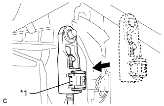
Text in Illustration *1 Lock Piece Install the cable end to the shift lever assembly.
Note
-
Check that the lock piece is pulled up.
-
Install the cable end all the way to the base of the pin.
-
-
Text in Illustration *1 Lock Piece *2 Adjuster Case *a Push in Push the lock piece into the adjuster case.
Note
Securely press in the lock piece until it locks.
-
After adjusting the shift lever position, check the operation and function of the shift lever. If there is a problem, adjust the position again.
-
Install the instrument cluster finish panel assembly and center instrument cluster finish panel sub- assembly Click here.
-