НАСОС СИСТЕМЫ ОХЛАЖДЕНИЯ СНЯТИЕ

-
DISCONNECT CABLE FROM NEGATIVE BATTERY TERMINAL
Note
When disconnecting the cable, some systems need to be initialized after the cable is reconnected Click here.
-
REMOVE FRONT WHEEL RH
-
REMOVE NO. 1 ENGINE UNDER COVER
-
REMOVE REAR ENGINE UNDER COVER RH
-
REMOVE RADIATOR COVER SUB-ASSEMBLY
-
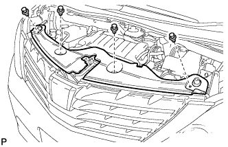
С помощью съемника фиксаторов освободите 4 фиксатора и снимите крышку радиатора в сборе.
-
-
DRAIN ENGINE COOLANT
CAUTION:
Не снимайте крышку расширительного бачка и пробку сливного крана радиатора, пока двигатель и радиатор не остынут. Выброс горячей охлаждающей жидкости и пара под давлением может стать причиной серьезных ожогов.
-

Обозначения на рисунке *1 Нижняя крышка двигателя № 1 *a Шланг Подсоедините шланг с внутренним диаметром 9 мм (0,354 дюйма) к сливному крану радиатора, как показано на рисунке.
-
Ослабьте пробку сливного крана радиатора.
-
Снимите крышку расширительного бачка. Затем слейте охлаждающую жидкость двигателя.
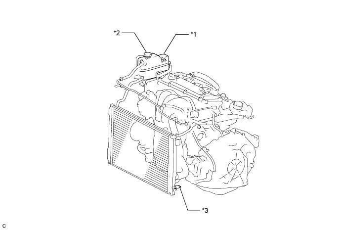
Обозначения на рисунке *1 Расширительный бачок системы охлаждения *2 Крышка расширительного бачка *3 Пробка сливного крана радиатора - - Tech Tips
Слейте охлаждающую жидкость двигателя в резервуар и утилизируйте ее в соответствии с местными требованиями.
-
Отсоедините шланг с внутренним диаметром 9 мм (0,354 дюйма) от сливного крана радиатора.
-
-
REMOVE RADIATOR RESERVE TANK ASSEMBLY
-
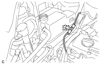
Отсоедините зажим жгута проводов.
-
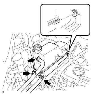
Отсоедините перепускные шланги охлаждающей жидкости № 1 и № 2.
-
Выверните болт и снимите расширительный бачок системы охлаждения в сборе.
-
-
REMOVE RADIATOR RESERVE TANK BRACKET
-
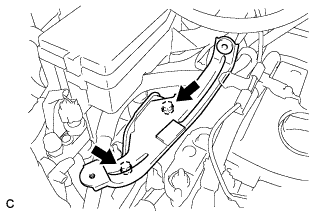
Выверните 2 болта и снимите кронштейн расширительного бачка системы охлаждения.
-
-
REMOVE V-RIBBED BELT
-

С помощью SST медленно поверните натяжитель поликлинового ремня по часовой стрелке.
- SST
- 09216-42010 ( 09216-04010 )
-
Снимите поликлиновой ремень со всех шкивов и медленно поверните натяжитель.
Note
-
Убедитесь, что SST и другие инструменты надежно закреплены на натяжителе.
-
Сжимая натяжитель поликлинового ремня, медленно поверните его.
-
Соблюдайте осторожность, чтобы ваши пальцы не попали между деталями.
-
-
-
REMOVE GENERATOR ASSEMBLY
-
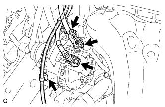
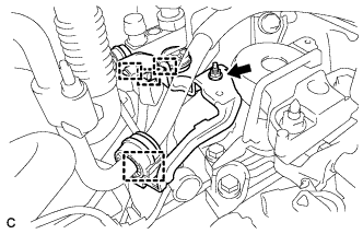
Disconnect the generator connector from the generator assembly.
-
Open the terminal cap.
-
Remove the nut and disconnect the wire harness from terminal B.
-
Remove the bolt and wire harness clamp bracket.
-
Disconnect the wire harness clamp.
-
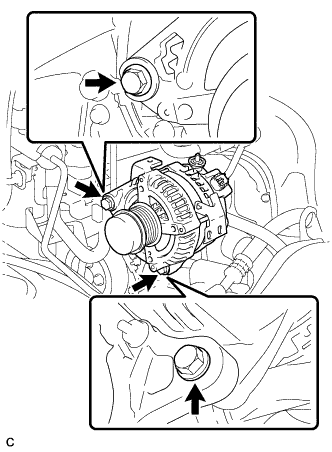
Remove the 2 bolts.
-
-
REMOVE ENGINE MOUNTING INSULATOR SUB-ASSEMBLY RH
-
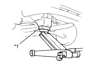
Text in Illustration *1 Wooden Block Place a wooden block on a jack underneath the engine.
-
Disconnect the 4 clamps.
-
Remove the nut and cooler pipe bracket.
-
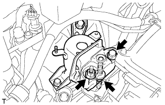
Remove the bolt and 2 nuts, then separate the engine mounting insulator sub-assembly RH from the engine mounting bracket RH.
-
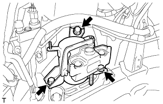
Remove the 3 bolts and engine mounting insulator sub-assembly RH.
-
-
REMOVE ENGINE MOUNTING SPACER
-
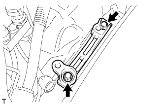
Remove the 2 bolts and engine mounting spacer.
-
-
REMOVE WATER PUMP PULLEY
-
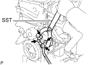
Using SST, remove the 4 bolts and water pump pulley.
- SST
- 09960-10010 ( 09962-01000, 09963-00700 )
-
-
REMOVE WATER PUMP ASSEMBLY (for TMC Made)
-
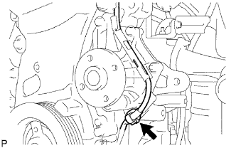
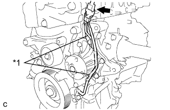
Remove the clamp of the crankshaft position sensor from the water pump.
-
Disconnect the wire of the crankshaft position sensor from the clamp bracket.
-
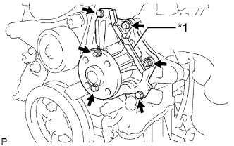
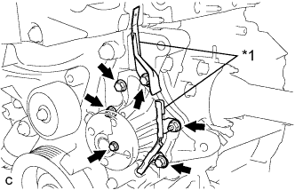
Text in Illustration *1 Clamp Bracket Remove the 4 bolts, 2 nuts and clamp bracket.
-
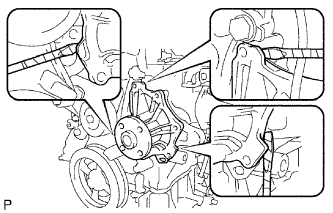
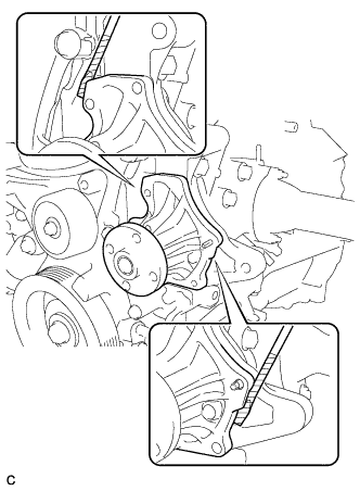
Using a screwdriver, pry between the water pump and cylinder block, and then remove the water pump.
Tech Tips
Tape the screwdriver tip before use.
Note
Be careful not to damage the contact surfaces of the water pump and cylinder block.
-
-
REMOVE WATER PUMP ASSEMBLY (except TMC Made)
-
Text in Illustration *1 Clamp Bracket Disconnect the connector of the crankshaft position sensor.
-
Disconnect the wire of the crankshaft position sensor from the clamp brackets.
-
Text in Illustration *1 Clamp Bracket Remove the 4 bolts, 2 nuts and 2 clamp brackets.
-
Using a screwdriver, pry between the water pump and cylinder block, and then remove the water pump.
Tech Tips
Tape the screwdriver tip before use.
Note
Be careful not to damage the contact surfaces of the water pump and cylinder block.
-