ТОПЛИВНАЯ ФОРСУНКА УСТАНОВКА
-
INSTALL FUEL INJECTOR ASSEMBLY
-
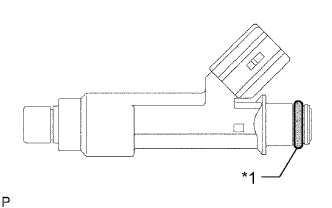
Text in Illustration *1 O-ring Apply a light coat of gasoline or spindle oil to new O-rings, then install them to each fuel injector.
-
Apply a light coat of gasoline or spindle oil to the part of the fuel delivery pipe which comes into contact with the O-ring of the fuel injector.
-
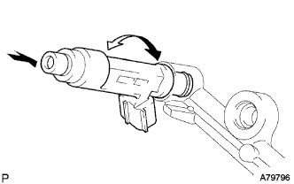
Push and twist each fuel injector to install them into the fuel delivery pipe.
Note
Make sure that the O-ring is not cracked or jammed before installing the injector.
-
Check that the fuel injector rotates smoothly. If the fuel injector does not rotate, replace the O-ring.
-
-
INSTALL FUEL DELIVERY PIPE SUB-ASSEMBLY
-
Install 4 new insulators into the cylinder head.
-
Install the 2 delivery pipe spacers onto the cylinder head.
-
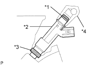
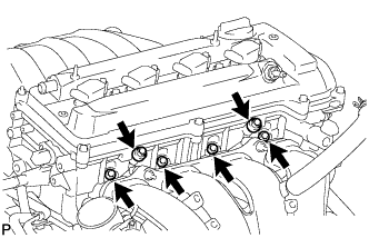
Text in Illustration *1 O-ring *2 Fuel Injector *3 Insulator *4 Fuel Delivery Pipe Install the fuel delivery pipe together with the 4 fuel injectors, then temporarily tighten the 2 bolts.
Note
Be careful not to drop the fuel injectors when installing the fuel delivery pipe.
-
Check that the fuel injector rotates smoothly.
If the fuel injector does not rotate smoothly, replace the O-ring.
-
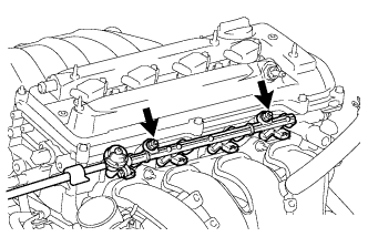
Tighten the 2 bolts to the specified torque.
- Torque:
- 20 N*m { 204 kgf*cm, 15 ft.*lbf }
-
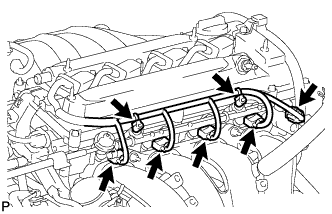
Connect the 4 fuel injector connectors.
-
Connect the oil control valve connector.
-
Install the 2 wire harness clamps.
-
-
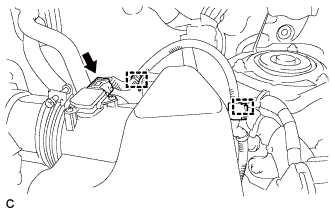
INSTALL NO. 2 VENTILATION HOSE
-
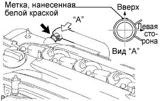
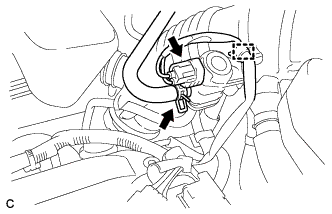
Connect the ventilation hose to the ventilation valve.
Note
Make sure that the paint mark and hose clamp are positioned as shown in the illustration after connecting the hose.
-
-
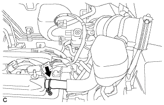
CONNECT FUEL TUBE SUB-ASSEMBLY
-
Install the fuel tube to the fuel hose clamp.
-

Push in the fuel tube connector to the fuel main tube until the fuel tube connector makes a "click" sound.
Note
-
Check that there is no damage or foreign matter on the fuel pipe connectors.
-
After connecting, check that the fuel tube connector and the pipe are securely connected by pulling on them.
-
-
Close the No. 1 fuel pipe clamp.
Tech Tips
The half connection prevention connector prevents the fuel hose connector cover from being locked if the fuel tube is not securely connected.
-
-
INSTALL AIR CLEANER CAP SUB-ASSEMBLY WITH HOSE
-
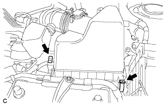
Установите крышку воздушного фильтра в сборе со шлангом и зафиксируйте 2 зажима.
-
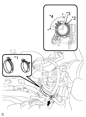
Обозначения на рисунке *1 Хомут шланга воздушного фильтра № 1 *2 Канавка *3 Выступ *4 95° Подсоедините шланг воздушного фильтра № 1 к корпусу дроссельной заслонки и расцепите замок хомута шланга воздушного фильтра № 1.
Note
-
Совместите канавку шланга воздушного фильтра с выступом на корпусе дроссельной заслонки и установите шланг.
-
Убедитесь, что выступ шланга воздушного фильтра № 1 находится в диапазоне, обозначенном *4
-
-
Подсоедините 2 зажима жгутов проводов и разъем датчика массового расхода воздуха.
-
Подсоедините вентиляционный шланг.
-
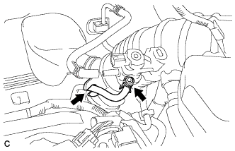
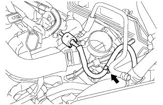
Подсоедините продувочный шланг к электровакуумному клапану № 1 в сборе и шлангу воздушного фильтра.
-
Подсоедините питающий шланг паров топлива к электровакуумному клапану № 1 в сборе.
-
Подсоедините зажим жгута проводов и разъем электровакуумного клапана № 1.
-
-
CONNECT CABLE TO NEGATIVE BATTERY TERMINAL
Note
When disconnecting the cable, some systems need to be initialized after the cable is reconnected Click here.
-
INSPECT FOR FUEL LEAK
-
Check fuel pump operation.
-
Connect the intelligent tester to the DLC3.
-
Turn the engine switch on (IG) and turn the intelligent tester on.
Note
Do not start the engine.
-
Enter the following menus: Powertrain / Engine / Active Test / Control the Fuel Pump / Speed.
-
Check for pressure in the fuel inlet tube from the fuel line. Check that sounds of fuel flowing in the fuel tank can be heard. If no sounds can be heard, check the integration relay, fuel pump, ECM and wiring connectors.
-
-
Inspect for fuel leaks.
-
Check that there is no fuel leakage after performing maintenance anywhere on the fuel system. If there is a fuel leak, repair or replace parts if necessary.
-
-
Turn the engine switch off.
-
Disconnect the intelligent tester from the DLC3.
-