РАСПРЕДВАЛ УСТАНОВКА

-
INSTALL CAMSHAFT TIMING GEAR ASSEMBLY
-
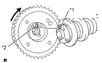
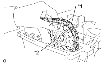
Text in Illustration *1 Straight Pin *2 Key Groove Put the camshaft timing gear and camshaft together with the straight pin and key groove misaligned, as shown in the illustration.
-
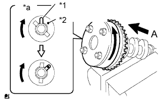
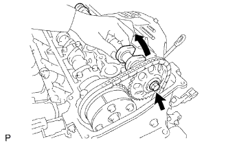
Text in Illustration *1 Straight Pin *2 Key Groove *a View A Turn the camshaft timing gear as shown in the illustration while pushing it gently against the camshaft. Push further at the position where the pin fits into the groove.
Note
Be sure not to turn the camshaft timing gear to the retard direction (clockwise).
-
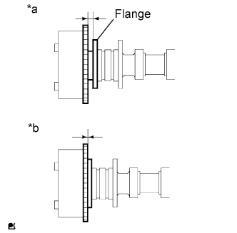
Text in Illustration *a Incorrect *b Correct Check that there is no clearance between the timing gear and camshaft flange.
-
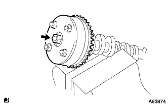
Tighten the flange bolt with the camshaft timing gear assembly fixed in place.
- Torque:
- 54 N*m { 551 kgf*cm, 40 ft.*lbf }
-
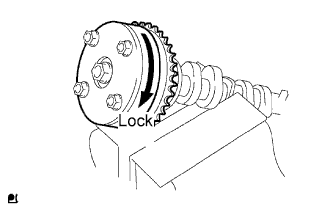
Check that the camshaft timing gear assembly can move to the retard direction (clockwise) and is locked in the most retarded position.
-
-
INSTALL CAMSHAFT
-
Apply a light coat of engine oil to the journal portion of the camshaft.
-
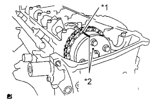
Text in Illustration *1 Paint Mark *2 Timing Mark Install the timing chain onto the camshaft timing gear with the paint mark aligned with the timing mark on the camshaft timing gear as shown in the illustration.
-
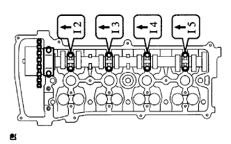
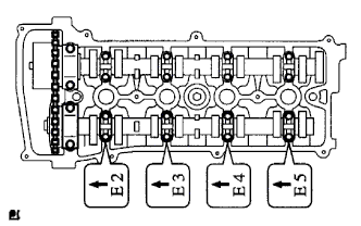
Examine the front marks and numbers, and check that the order is as shown in the illustration. Then install the bearing caps into the cylinder head.
-
Apply a light coat of engine oil on the threads and under the heads of the bearing cap bolts.
-
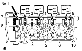
Using several steps, uniformly tighten the 10 bearing cap bolts in the sequence shown in the illustration.
- Torque:
- No. 1 bearing
- 30 N*m { 301 kgf*cm, 22 ft.*lbf }
- No. 3 bearing
- 9.0 N*m { 92 kgf*cm, 80 in.*lbf }
-
-
INSTALL NO. 2 CAMSHAFT
-
Text in Illustration *1 Paint Mark *2 Timing Mark Apply a light coat of engine oil to the journal portion of the No. 2 camshaft.
-
Put the No. 2 camshaft on the cylinder head with the paint mark on the chain aligned with the timing mark on the camshaft timing sprocket.
-
While holding the No. 2 camshaft by hand, temporarily tighten the camshaft timing sprocket set bolt.
-
Examine the front marks and numbers, and check that the order is as shown in the illustration. Then install the bearing caps onto the cylinder head.
-
Apply a light coat of engine oil to the threads and under the heads of the bearing cap bolts.
-
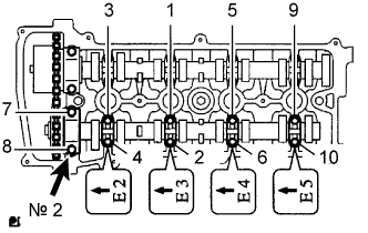
Using several steps, uniformly tighten the 10 bearing cap bolts in the sequence shown in the illustration.
- Torque:
- No. 2 bearing
- 30 N*m { 301 kgf*cm, 22 ft.*lbf }
- No. 3 bearing
- 9.0 N*m { 92 kgf*cm, 80 in.*lbf }
-
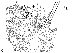
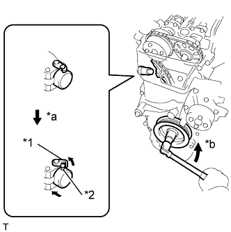
Text in Illustration *a Tighten *b Hold Using a union nut wrench, while holding the camshaft with a wrench, tighten the camshaft timing sprocket set bolt.
- Torque:
- 54 N*m { 551 kgf*cm, 40 ft.*lbf }
Note
-
Be careful not to damage the valve lifter.
-
Use the formula to calculate special torque values for situations where union nut wrench is combined with a torque wrench Click here.
-
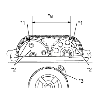
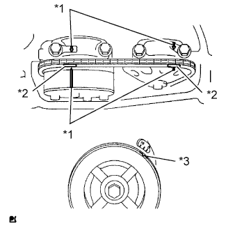
Text in Illustration *1 Paint Mark *2 Timing Mark *3 Groove *a 7 Links Check that the paint marks on the chain are aligned with the timing marks on the camshaft timing gear and camshaft timing sprocket. Also, check that the crankshaft pulley groove is aligned with the timing mark "0" on the timing mark chain cover.
-
-
INSTALL NO. 1 CHAIN TENSIONER ASSEMBLY
-
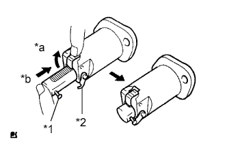
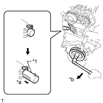
Text in Illustration *1 Pin *2 Hook *a Raise *b Push Release the ratchet pawl, then fully push in the plunger and set the hook to the pin so that the plunger is in the position shown in the illustration.
-
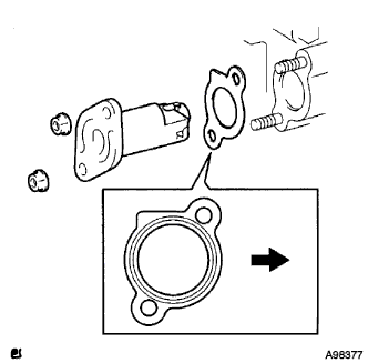
Install a new gasket and the chain tensioner with the 2 nuts.
- Torque:
- 9.0 N*m { 92 kgf*cm, 80 in.*lbf }
Note
When installing the chain tensioner, set the hook again if the hook releases the plunger.
Text in Illustration 
Engine Front -
Text in Illustration *1 Hook *2 Pin *a Disconnect *b Turn Turn the crankshaft counterclockwise, then disconnect the hook from the pin.
-
Text in Illustration *1 Plunger *a Extend *b Turn Turn the crankshaft clockwise, then check that the plunger is extended.
-
-
SET NO. 1 CYLINDER TO TDC/COMPRESSION
-
Text in Illustration *1 Timing Mark *2 Paint Mark *3 Groove Turn the crankshaft pulley until the groove and the timing mark "0" on the timing chain cover are aligned.
-
Check that each timing mark on the camshaft timing gear and sprocket is aligned with each timing mark located on the No. 1 and No. 2 bearing caps as shown in the illustration.
If not, turn the crankshaft pulley 1 revolution (360°) to align the timing marks as illustrated.
-
Place paint marks on the chain in alignment with the timing marks on the camshaft timing gear and camshaft timing sprocket.
-
-
CHECK VALVE CLEARANCE
-
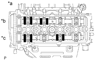
Text in Illustration *a No. 1 Cylinder TDC/Compression *b Intake *c Exhaust Check only the valves indicated in the illustration.
-
Using a feeler gauge, measure the clearance between the valve lifter and camshaft.
Standard Valve Clearance (Cold) Item Specified Condition Intake 0.19 to 0.29 mm (0.00748 to 0.0114 in.) Exhaust 0.38 to 0.48 mm (0.0150 to 0.0189 in.) -
Record any out-of-specification valve clearance measurements. They will be used later to determine the required replacement valve clearance lifters.
-
-
Turn the crankshaft 1 revolution (360°) and set the No. 4 cylinder to TDC/Compression.
-
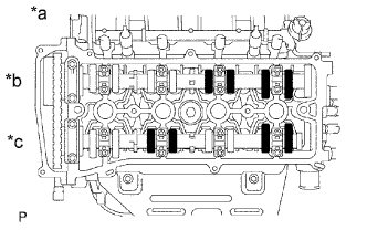
Text in Illustration *a No. 4 Cylinder TDC/Compression *b Intake *c Exhaust Check only the valves indicated in the illustration.
-
Using a feeler gauge, measure the clearance between the valve lifter and camshaft.
Standard Valve Clearance (Cold) Item Specified Condition Intake 0.19 to 0.29 mm (0.00748 to 0.0114 in.) Exhaust 0.38 to 0.48 mm (0.0150 to 0.0189 in.) -
Record any out-of-specification valve clearance measurements. They will be used later to determine the required replacement valve lifters.
-
-
-
ADJUST VALVE CLEARANCE
-
Set No. 1 cylinder to TDC/compression Click here.
-
Remove the No. 1 chain tensioner Click here.
-
Loosen the camshaft timing sprocket Click here.
-
Remove the No. 2 camshaft Click here.
-
Remove the camshaft Click here.
-
Remove the valve lifters.
-
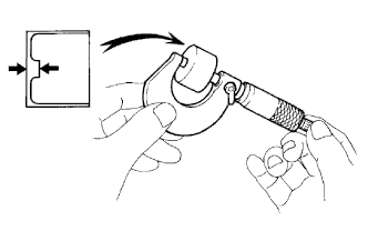
Using a micrometer, measure the thickness of the removed valve lifters.
-
Calculate the thickness of a new lifter so that the valve clearance comes within the specified values.
New Lifter Thickness Item Specification Intake A = B + (C - 0.24 mm (0.00945 in.)) Exhaust A = B + (C - 0.43 mm (0.0169 in.)) A New lifter thickness B Used lifter thickness C Measured valve clearance CALCULATION EXAMPLE (Intake):
-
Measured intake valve clearance = 0.40 mm (0.0157 in.)
(Measured - Specification = Excess clearance)
-
0.40 mm (0.0157 in.) - 0.24 mm (0.00945 in.) = 0.16 mm (0.00630 in.)
-
Measured used lifter thickness = 5.250 mm (0.2067 in.)
-
New lifter thickness = 5.410 mm (0.2130 in.)
(Excess clearance + Used lifter thickness = Ideal new lifter)
-
0.16 mm (0.00630 in.) + 5.250 mm (0.2067 in.) = 5.410 mm (0.2130 in.)
-
Closest new lifter = 5.420 mm (0.2134 in.)
-
Select No. 42 lifter
-
-
Select a new lifter with a thickness as close as possible to the calculated values.
Tech Tips
-
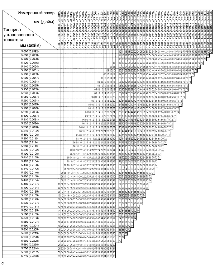
Lifters are available in 35 sizes in increments of 0.020 mm (0.000787 in.), from 5.060 to 5.740 mm (0.1992 to 0.2260 in.).
-
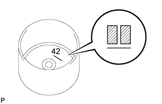
The identification number inside the valve lifters shows the value to 2 decimal places. (The illustration shows 5.420 mm (0.2134 in.)
-
-
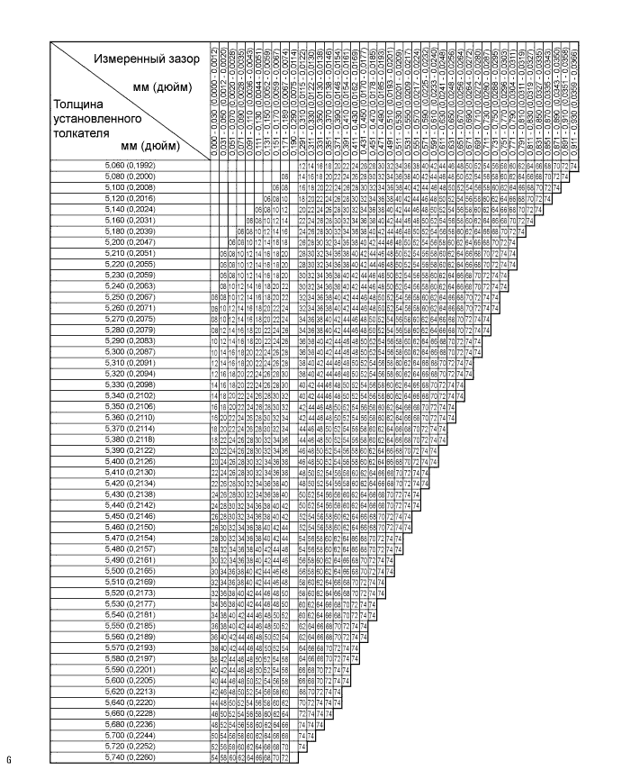
Valve lifter selection chart (intake).
New Lifter Thickness Lifter No. Thickness
mm (in.)
Lifter No. Thickness
mm (in.)
Lifter No. Thickness
mm (in.)
06 5.060 (0.1992) 30 5.300 (0.2087) 54 5.540 (0.2181) 08 5.080 (0.2000) 32 5.320 (0.2094) 56 5.560 (0.2189) 10 5.100 (0.2008) 34 5.340 (0.2102) 58 5.580 (0.2197) 12 5.120 (0.2016) 36 5.360 (0.2110) 60 5.600 (0.2205) 14 5.140 (0.2024) 38 5.380 (0.2118) 62 5.620 (0.2213) 16 5.160 (0.2031) 40 5.400 (0.2126) 64 5.640 (0.2220) 18 5.180 (0.2039) 42 5.420 (0.2134) 66 5.660 (0.2228) 20 5.200 (0.2047) 44 5.440 (0.2142) 68 5.680 (0.2236) 22 5.220 (0.2055) 46 5.460 (0.2150) 70 5.700 (0.2244) 24 5.240 (0.2063) 48 5.480 (0.2157) 72 5.720 (0.2252) 26 5.260 (0.2071) 50 5.500 (0.2165) 74 5.740 (0.2260) 28 5.280 (0.2079) 52 5.520 (0.2173) - - Standard intake valve clearance (cold) 0.19 to 0.29 mm (0.00748 to 0.0114 in.) EXAMPLE:
The 5.250 mm (0.2067 in.) lifter is installed, and the measured clearance is 0.400 mm (0.0157 in.). Replace the 5.250 mm (0.2067 in.) lifter with a new No. 42 lifter.
-
Valve lifter selection chart (exhaust).
New Lifter Thickness Lifter No. Thickness
mm (in.)
Lifter No. Thickness
mm (in.)
Lifter No. Thickness
mm (in.)
06 5.060 (0.1992) 30 5.300 (0.2087) 54 5.540 (0.2181) 08 5.080 (0.2000) 32 5.320 (0.2094) 56 5.560 (0.2189) 10 5.100 (0.2008) 34 5.340 (0.2102) 58 5.580 (0.2197) 12 5.120 (0.2016) 36 5.360 (0.2110) 60 5.600 (0.2205) 14 5.140 (0.2024) 38 5.380 (0.2118) 62 5.620 (0.2213) 16 5.160 (0.2031) 40 5.400 (0.2126) 64 5.640 (0.2220) 18 5.180 (0.2039) 42 5.420 (0.2134) 66 5.660 (0.2228) 20 5.200 (0.2047) 44 5.440 (0.2142) 68 5.680 (0.2236) 22 5.220 (0.2055) 46 5.460 (0.2150) 70 5.700 (0.2244) 24 5.240 (0.2063) 48 5.480 (0.2157) 72 5.720 (0.2252) 26 5.260 (0.2071) 50 5.500 (0.2165) 74 5.740 (0.2260) 28 5.280 (0.2079) 52 5.520 (0.2173) - - Standard exhaust valve clearance (cold) 0.38 to 0.48 mm (0.0150 to 0.0189 in.) EXAMPLE:
The 5.340 mm (0.2102 in.) lifter is installed, and the measured clearance is 0.510 mm (0.0201 in.). Replace the 5.340 mm (0.2102 in.) lifter with a new No. 42 lifter.
-
Install the selected valve lifter.
-
Install the camshaft Click here.
-
Install the No. 2 camshaft Click here.
-
Install the No. 1 chain tensioner Click here.
-
-
INSTALL CYLINDER HEAD COVER SUB-ASSEMBLY
-
Remove any old packing material from the contact surfaces.
-
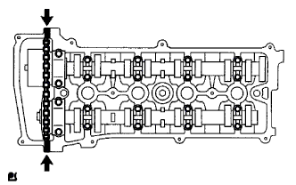
Apply seal packing to the 2 locations shown in the illustration.
Seal packing Toyota Genuine Seal Packing Black, Three Bond 1207B or equivalent Note
-
Remove any oil from the contact surfaces.
-
Install the oil pan within 3 minutes of applying seal packing.
-
Do not add engine oil for at least 2 hours after installing the oil pan.
-
-
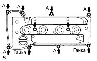
Install the cylinder head cover gasket and sub-assembly with the 8 bolts and 2 nuts.
- Torque:
- Bolt A
- 11 N*m { 112 kgf*cm, 8 ft.*lbf }
- Bolt B
- 14 N*m { 143 kgf*cm, 10 ft.*lbf }
- Nut
- 11 N*m { 112 kgf*cm, 8 ft.*lbf }
-
Install the engine wire harness with the 3 bolts.
- Torque:
- 8.4 N*m { 86 kgf*cm, 74 in.*lbf }
-
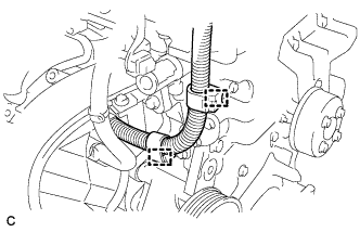
Connect the 2 wire harness clamps.
-
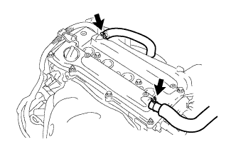
Connect the 2 ventilation hoses to the cylinder head cover.
-
-
INSTALL SPARK PLUG
-
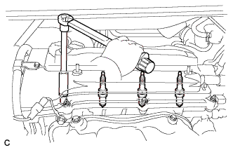
Install the 4 spark plugs.
- Torque:
- 19 N*m { 194 kgf*cm, 14 ft.*lbf }
-
-
INSTALL IGNITION COIL ASSEMBLY
-
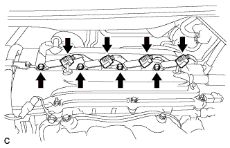
Install the 4 ignition coils with the 4 bolts.
- Torque:
- 9.0 N*m { 92 kgf*cm, 80 in.*lbf }
-
Connect the 4 ignition coil connectors.
-
-
INSTALL RADIATOR RESERVE TANK BRACKET
-
Установите кронштейн расширительного бачка системы охлаждения и закрепите его 2 болтами.
- Torque:
- 12 Н*м { 122 кгс*см, 9 фунт-сила-футов }
-
-
INSTALL RADIATOR RESERVE TANK ASSEMBLY
-
Установите расширительный бачок системы охлаждения в сборе на кронштейн расширительного бачка системы охлаждения.
- Torque:
- 12 Н*м { 122 кгс*см, 9 фунт-сила-футов }
-
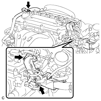
Подсоедините перепускные шланги охлаждающей жидкости № 1 и № 2.
-
Подсоедините зажим жгута проводов к расширительному бачку системы охлаждения в сборе.
-
-
INSTALL RADIATOR COVER SUB-ASSEMBLY
-
Закрепите крышку радиатора в сборе 4 фиксаторами.
-
-
INSTALL OUTER COWL TOP PANEL SUB-ASSEMBLY
-
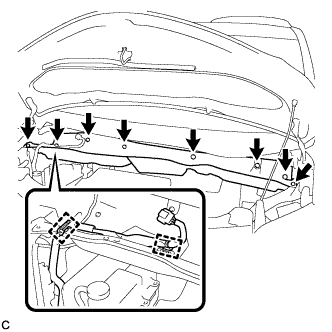
Установите наружную верхнюю панель кожуха и закрепите ее 8 болтами.
- Torque:
- 8,8 Н*м { 90 кгс*см, 78 фунт-сила-дюймов }
-
Подсоедините 2 зажима к наружной верхней панели кожуха.
-
Удалите защитную ленту.
-
-
INSTALL BRAKE MASTER CYLINDER RESERVOIR ASSEMBLY
-

Закрепите бачок главного цилиндра тормозной системы с кронштейном на наружной верхней панели кожуха с помощью 2 гаек.
- Torque:
- 6,5 Н*м { 66 кгс*см, 58 фунт-сила-дюймов }
-
-
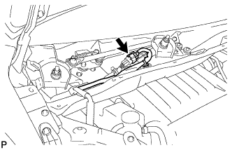
INSTALL WINDSHIELD WIPER MOTOR AND LINK
-
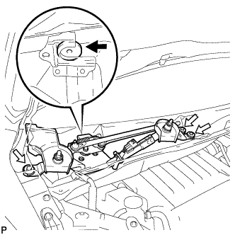
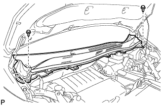
Установите электродвигатель стеклоочистителя ветрового стекла с тягой в сборе и закрепите его 3 болтами, как показано на рисунке.
- Torque:
- 5,5 Н*м { 56 кгс*см, 49 фунт-сила-дюймов }
-
Подсоедините разъем.
-
-
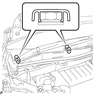
INSTALL COWL TOP VENTILATOR LOUVER SUB-ASSEMBLY
-
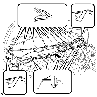
Введите в зацепление 15 захватов и 2 направляющие и установите вентиляционную решетку в верхней части кожуха в сборе, как показано на рисунке.
-
Установите 2 фиксатора.
-
-
INSTALL WINDSHIELD WIPER ARM AND BLADE ASSEMBLY LH
-
При повторном использовании левого рычага переднего стеклоочистителя со щеткой в сборе:
-
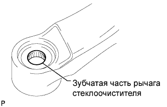
Очистите зубчатую часть рычага стеклоочистителя.
-
-
При повторном использовании тяги стеклоочистителя ветрового стекла в сборе:
-
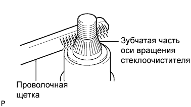
Почистите зубчатую часть оси вращения стеклоочистителя проволочной щеткой.
-
-
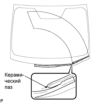
Установите левый рычаг переднего стеклоочистителя со щеткой в сборе, как показано на рисунке, и закрепите их гайкой.
- Torque:
- 24 Н*м { 245 кгс*см, 18 фунт-сила-футов }
-
Приведите в действие передние стеклоочистители, одновременно распыляя омывающую жидкость на ветровое стекло. Убедитесь, что передние стеклоочистители работают надлежащим образом и не задевают кузов автомобиля.
-
-
INSTALL WINDSHIELD WIPER ARM AND BLADE ASSEMBLY RH
-
Приведите в действие стеклоочиститель и остановите электродвигатель стеклоочистителя ветрового стекла в положении автоматического ограничения хода.
-
При повторном использовании правого рычага переднего стеклоочистителя со щеткой в сборе:
-
Очистите зубчатую часть рычага стеклоочистителя.
-
-
При повторном использовании тяги стеклоочистителя ветрового стекла в сборе:
-
Почистите зубчатую часть оси вращения стеклоочистителя проволочной щеткой.
-
-
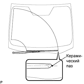
Установите правый рычаг переднего стеклоочистителя со щеткой в сборе, как показано на рисунке, и закрепите их гайкой.
- Torque:
- 24 Н*м { 245 кгс*см, 18 фунт-сила-футов }
-
-
INSTALL WINDSHIELD WIPER ARM COVER
-
Закрепите 2 захвата и установите 2 крышки рычага стеклоочистителя ветрового стекла.
-
-
ADD ENGINE OIL
-
Clean and install the oil drain plug with a new gasket.
- Torque:
- 40 N*m { 408 kgf*cm, 29 ft.*lbf }
-
Add new engine oil.
Standard Oil Grade Oil Grade Oil Viscosity (SAE) API grade SL "Energy-Conserving", SM "Energy-Conserving", SN "Resource-Conserving" or ILSAC multigrade engine oil
-
0W-20
-
5W-20
-
5W-30
-
10W-30
API grade SL, SM or SN multigrade engine oil
-
15W-40
-
20W-50
Standard Oil Grade (Destination package for Philippines) Oil Grade Oil Viscosity (SAE) API grade SL "Energy-Conserving", SM "Energy-Conserving", SN "Resource-Conserving" or ILSAC multigrade engine oil
-
5W-30
-
10W-30
API grade SL, SM or SN multigrade engine oil
-
15W-40
-
20W-50
Standard Oil Capacity Item Standard Condition Drain and refill with oil filter change 4.3 liters (4.5 US qts, 3.8 Imp. qts) Drain and refill without oil filter change 4.1 liters (4.3 US qts, 3.6 Imp. qts) Dry fill 5.0 liters (5.3 US qts, 4.4 Imp. qts) -
-
Install the oil filler cap.
-
-
INSPECT FOR OIL LEAK
-
INSPECT IGNITION TIMING
Note
-
Turn all the electrical systems and the A/C off.
-
When checking the ignition timing, the transaxle should be in neutral or park.
-
Warm up and stop the engine.
-
When using the intelligent tester:
-
Connect the intelligent tester to the DLC3.
-
Turn the engine switch on (IG).
-
Turn the intelligent tester on.
-
Enter the following menus: Power Train / Engine and ECT / Data List / IGN Advance
-
Start the engine.
-
According to the display on the intelligent tester, read the Data List.
Standard ignition timing 8 to 16° BTDC at idle -
Check that the ignition timing advances immediately when the engine speed is increased.
-
Turn the engine switch off.
-
Disconnect the intelligent tester from the DLC3.
-
-
When not using the intelligent tester:
-
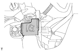
Open the ignition cover located to the right of the No. 4 ignition coil.
-
Pull the wire harness out from the IG cover.
-
Connect the timing light to the wire harness.
Note
Use a timing light that detects the primary signal.
-
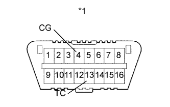
Text in Illustration *1 DLC3 Using SST, connect terminals 13 (TC) and 4 (CG) of the DLC3.
- SST
- 09843-18040
-
Allow the engine to idle and check the ignition timing.
Standard ignition timing 8 to 12° BTDC at idle Tech Tips
Run the engine at 1000 to 1300 rpm for 5 seconds, then check that the engine speed returns to idle speed.
-
Disconnect SST from terminals 13 (TC) and 4 (CG) of the DLC3.
-
Allow the engine to idle and check the ignition timing.
Standard ignition timing 8 to 16° BTDC at idle -
Check that the ignition timing advances immediately when the engine speed is increased.
-
Turn the engine switch off.
-
Remove the timing light.
-
Close the IG cover.
-
-
-
INSTALL REAR ENGINE UNDER COVER RH
-
INSTALL FRONT WHEELS
- Torque:
- 103 N*m { 1050 kgf*cm, 76 ft.*lbf }
-
CONNECT CABLE FROM NEGATIVE BATTERY TERMINAL
Note
When disconnecting the cable, some systems need to be initialized after the cable is reconnected Click here.