- Click here
INSPECT FUEL INJECTOR ASSEMBLY
-
Inspect the resistance.
-
Measure the resistance according to the value(s) in the table below.
Standard Resistance Tester Connection Condition Specified Condition 1 - 2 20°C (68°F) 11.6 to 12.4 Ω If the result is not as specified, replace the fuel injector assembly.
-
-
- Click here
INSPECT INJECTION VOLUME AND LEAKAGE
CAUTION:
-
This test involves high-pressure fuel and electricity.
-
Take every precaution regarding safe handling of both the fuel and the electrical parts.
-
Perform this test in a safe area, and avoid any sparks or flame.
-
Do not smoke.
-
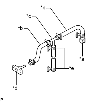
Assemble SST as shown in the illustration.
09268-31014 09268-41091 09268-41120 09268-41500 09268-41700 95336-08070 Table 1. Text in Illustration *a SST (Fuel Tube Connector) *b SST (Hose) *c SST (3 Way) *d SST (Union No. 7) *e SST (Hose Band) -
Discharge the fuel system pressure (Click here).
-
Disconnect the No. 1 fuel hose (fuel tube connector) from the fuel tube.
-
Remove the 2 bolts and disconnect the fuel pressure regulator assembly from the fuel delivery pipe sub-assembly.
Note:Do not disconnect the No. 2 fuel hose from the fuel pressure regulator assembly.
-
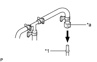
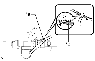
Connect SST to the fuel tube.
Table 2. Text in Illustration *1 Fuel Tube *a SST (Fuel Tube Connector) CAUTION:Always read the precautions (Click here) before connecting the fuel tube connector (quick type).
-
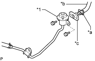
Connect SST to the fuel pressure regulator assembly fuel inlet with the 2 bolts.
09268-31014 09268-41091 09268-41700 95336-08070 8.5 N*m 87 kgf*cm 75 in.*lbf Table 3. Text in Illustration *1 Fuel Pressure Regulator Assembly *a SST (Hose Band) *b SST (Hose) *c SST (Union No. 7) -
Install the O-ring to the fuel injector assembly.
-
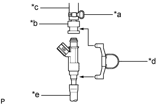
Assemble SST as shown in the illustration.
09268-31014 09268-41110 09268-41310 09268-41700 95336-08070 Table 4. Text in Illustration *a SST (Hose Band) *b SST (Adapter) *c SST (Hose) *d SST (Clamp) *e Vinyl Tube Note:Make sure that SST (adapter) and SST (clamp) are not loose and do not rattle.
-
Pass SST (tie band) through the loop on the handle of SST (clamp) to secure SST (clamp) to SST (adapter).
09268-31014 09268-41800 Table 5. Text in Illustration *a SST (Tie Band) *b Lock Note:
-
As SST (tie band) does not completely prevent SST (clamp) from becoming loose, do not subject the parts to any impacts while using them.
-
Before using SST (tie band), make sure that there is no deterioration, damage or cracks. If there are any abnormalities, replace SST.
Tip:When removing SST (tie band), disengage the lock.
-
-
Check that SST (clamp) and SST (adapter) cannot be easily separated.
-
Install a vinyl tube to the fuel injector assembly.
-
Put the fuel injector assembly into a graduated cylinder.
Note:Install a suitable vinyl tube onto the fuel injector assembly to contain the gasoline spray.
-
Operate the fuel pump.
-
Turn the ignition switch to ON.
Note:Do not start the engine.
-
Turn the intelligent tester on.
-
Enter the following menus: Powertrain / Engine and ECT / Active Test / Control the Fuel Pump / Speed.
-
-
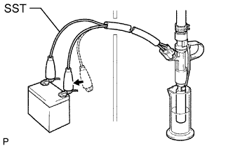
Connect SST (EFI inspection wire H) to the fuel injector assembly and the battery for 15 seconds, and measure the injection volume with a graduated cylinder. Test each injector 2 or 3 times.
09842-30080 Standard injection volume 71 to 86 cm3 (4.3 to 5.2 cu. in.) in 15 seconds Standard difference between each fuel injector assembly 15 cm3 (0.9 cu. in.) or less Note:Always turn the voltage on and off on the battery side, not the fuel pump side.
If the result is not as specified, replace the fuel injector assembly.
-
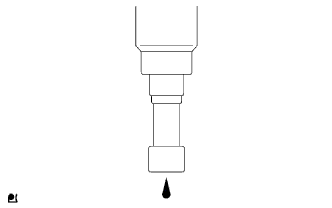
Check the fuel leakage.
-
In the condition above, disconnect the test probes of SST (EFI inspection wire H) from the battery and check the fuel leakage rate from the fuel injector assembly.
Standard fuel drop 1 drop or less per 12 minutes
-
-