REAR DIFFERENTIAL SIDE GEAR SHAFT OIL SEAL INSTALLATION
-
INSTALL REAR DIFFERENTIAL SIDE GEAR SHAFT OIL SEAL
-
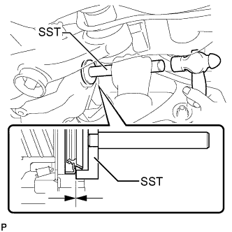
Using SST and a hammer, install a new rear differential side gear shaft oil seal until it is flush with the carrier end surface.
- SST
- 09550-00032
- 09950-70010 ( 09951-07200 )
Oil seal driven in depth 0 +/- 0.5 mm (0 +/- 0.019 in.) -
Apply MP grease to the rear differential side gear shaft oil seal lip.
-
-
INSTALL REAR DRIVE SHAFT SNAP RING
-
Install a new rear drive shaft snap ring.
-
-
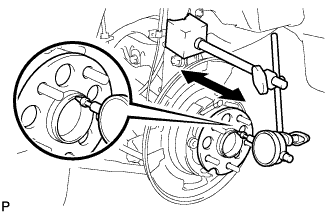
INSTALL REAR DRIVE SHAFT ASSEMBLY
-
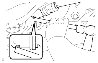
Align the shaft splines and install the rear drive shaft assembly with a brass bar and hammer.
Note
-
Set the snap ring with the opening facing downward.
-
Be careful not to damage the oil seal, boot, or dust cover.
-
Install the drive shaft assembly while keeping it level.
-
-
-
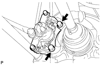
TEMPORARILY INSTALL REAR STRUT ROD ASSEMBLY
-
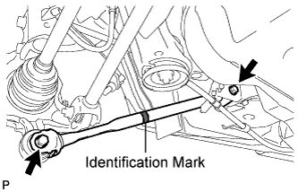
Check that the identification mark of the rear strut rod assembly is positioned on the inner side of the vehicle.
-
Temporarily install the rear strut rod assembly with the 2 bolts and the 2 nuts.
Note
Since stopper nuts are used, temporarily tighten the bolts.
-
-
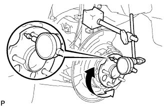
INSTALL REAR AXLE HUB AND BEARING ASSEMBLY
-
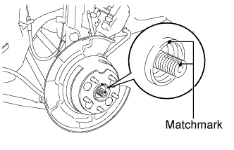
Align the matchmarks on the drive shaft and rear axle hub.
Note
Do not rotate the drive shaft.
-
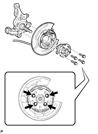
Install the parking brake assembly and the rear axle hub and bearing assembly with the 4 bolts.
- Torque:
- 75 N*m { 764 kgf*cm, 55 ft.*lbf }
Note
Do not twist the No. 3 parking brake cable assembly when installing it.
-
-
INSTALL REAR DISC
-
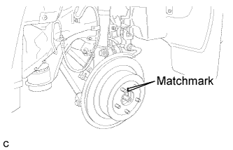
Align matchmarks and install the rear disc.
Note
When replacing the rear disc with a new one, select the installation position where the rear disc has minimal runout.
-
-
INSTALL REAR DISC BRAKE CALIPER ASSEMBLY
-
Install the rear disc brake caliper assembly with the 2 bolts.
- Torque:
- 78 N*m { 795 kgf*cm, 57 ft.*lbf }
-
-
TEMPORARILY TIGHTEN REAR AXLE SHAFT NUT
-
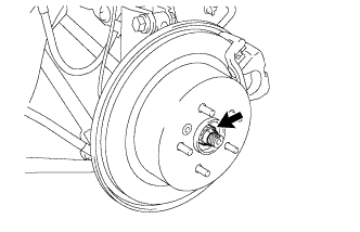
Clean the threaded parts on the rear drive shaft assembly and rear axle shaft nut using a non-residue solvent.
Note
-
Be sure to perform this work for a new rear drive shaft assembly.
-
Keep the threaded parts free of oil and foreign objects.
-
-
While applying the brakes, temporarily install a new rear axle shaft nut.
- Torque:
- 294 N*m { 2996 kgf*cm, 216 ft.*lbf }
Note
Stake the nut after inspecting for looseness and runout in the following steps.
-
-
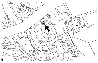
INSTALL REAR SPEED SENSOR
-
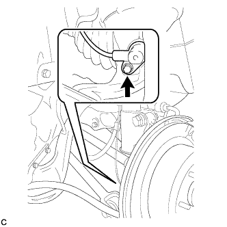
Install the rear speed sensor to the rear axle carrier sub-assembly with the bolt .
- Torque:
- 8.0 N*m { 82 kgf*cm, 71 in.*lbf }
Note
-
Keep the rear speed sensor tip and sensor installation hole free from foreign matter.
-
To prevent interference with the bearing rotor, do not rotate the rear speed sensor body when inserting the rear speed sensor body or after inserting the rear speed sensor body.
-
Do not twist the rear speed sensor wire when installing.
-
-
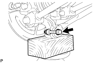
STABILIZE SUSPENSION
-
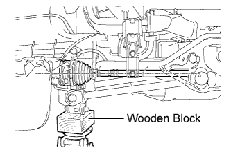
Jack up the rear axle carrier sub-assembly, placing a wooden block underneath to avoid damage. Apply load to the suspension so that the rear drive shaft assembly is positioned horizontally.
CAUTION:
Do not jack up the rear axle carrier sub-assembly too high as the vehicle may fall.
Note
Do not bend the brake dust cover.
Tech Tips
-
If the rear drive shaft assembly cannot be positioned horizontally as shown in the illustration even when the rear axle carrier sub-assembly is jacked up, apply additional load to the vehicle such as by having a person sit in the rear seat.
-
Use the same procedure for the RH side and LH side.
-
-
-
FULLY TIGHTEN NO. 2 REAR SUSPENSION ARM ASSEMBLY
-
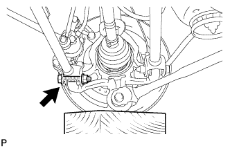
Fully tighten the rear No. 2 suspension arm assembly with the bolt and nut.
- Torque:
- 112 N*m { 1141 kgf*cm, 82 ft.*lbf }
Note
-
Since a stopper nut is used, fully tighten the bolt.
-
The final torque must be applied under standard vehicle height conditions.
-
-
FULLY TIGHTEN NO. 1 REAR SUSPENSION ARM ASSEMBLY
-
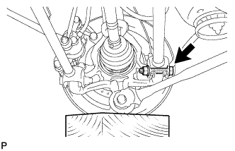
Fully tighten the rear No. 1 suspension arm assembly with the bolt and nut.
- Torque:
- 112 N*m { 1141 kgf*cm, 82 ft.*lbf }
Note
-
Since a stopper nut is used, fully tighten the bolt.
-
The final torque must be applied under standard vehicle height conditions.
-
-
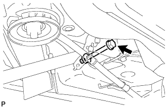
FULLY TIGHTEN REAR STRUT ROD ASSEMBLY
-
Fully tighten the bolt.
- Torque:
- 80 N*m { 815 kgf*cm, 59 ft.*lbf }
Note
-
Since a stopper nut is used, fully tighten the bolt.
-
The final torque must be applied under standard vehicle height conditions.
-
Fully tighten the bolt.
- Torque:
- 80 N*m { 815 kgf*cm, 59 ft.*lbf }
Note
-
Since a stopper nut is used, fully tighten the bolt.
-
The final torque must be applied under standard vehicle height conditions.
-
-
INSTALL NO. 3 PARKING BRAKE CABLE ASSEMBLY
-
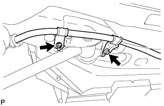
Install the No. 3 parking brake cable assembly with the bolt and the nut.
- Torque:
- Bolt
- 39 N*m { 397 kgf*cm, 29 ft.*lbf }
- Nut
- 6.0 N*m { 61 kgf*cm, 53 in.*lbf }
Note
Do not twist the No. 3 parking brake cable assembly when installing it.
-
-
SEPARATE REAR DISC BRAKE CALIPER ASSEMBLY
-
Remove the 2 bolts and separate the rear disc brake caliper assembly.
Note
Use wire or an equivalent tool to keep the brake caliper from hanging down by the flexible hose.
-
-
REMOVE REAR DISC
-
Put matchmarks on the rear disc and the axle hub.
-
Release the parking brake and remove the rear disc.
Tech Tips
If the disc cannot be removed easily, turn and press firmly the shoe adjuster until the wheel comes free.
-
-
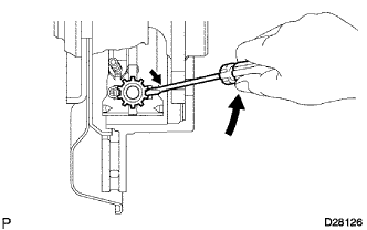
INSPECT REAR AXLE HUB BEARING LOOSENESS
-
Using a dial indicator, check for looseness near the center of the rear axle hub and bearing assembly.
Maximum looseness 0 mm (0 in.) Note
Ensure that the dial indicator is set perpendicular to the measurement surface.
Tech Tips
If the looseness exceeds the maximum, replace the rear axle hub and bearing assembly.
-
-
INSPECT REAR AXLE HUB RUNOUT
-
Using a dial indicator, check for runout on the surface of the rear axle hub and bearing assembly outside the rear axle hub bolt.
Maximum runout 0.08 mm (0.0031 in.) Note
Ensure that the dial indicator is set perpendicular to the measurement surface.
Tech Tips
If the runout exceeds the maximum, replace the rear axle hub and bearing assembly.
-
-
INSTALL REAR DISC
-
Align matchmarks and install the rear disc.
Note
When replacing the rear disc with a new one, select the installation position where the rear disc has minimal runout.
-
-
INSTALL REAR DISC BRAKE CALIPER ASSEMBLY
-
Install the rear disc brake caliper assembly with the 2 bolts.
- Torque:
- 78 N*m { 795 kgf*cm, 57 ft.*lbf }
-
-
INSTALL REAR AXLE SHAFT NUT
-
Clean the threaded parts on the drive shaft and axle hub nut using a non-residue solvent.
Note
-
Be sure to perform this work for a new drive shaft.
-
Keep the threaded parts free of oil and foreign objects.
-
-
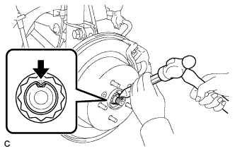
Install a new rear axle shaft nut.
- Torque:
- 294 N*m { 2996 kgf*cm, 216 ft.*lbf }
-
Using a chisel and hammer, stake the rear axle shaft nut.
-
-
INSTALL REAR DIFFERENTIAL DRAIN PLUG
-
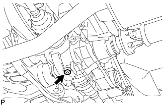
Using a hexagon wrench (10 mm), install the filler plug with a new gasket.
- Torque:
- 49 N*m { 500 kgf*cm, 36 ft.*lbf }
-
-
ADD DIFFERENTIAL OIL
-
Fill the rear differential carrier assembly with hypoid gear oil.
-
-
INSPECT DIFFERENTIAL OIL
-
Stop the vehicle on a level place.
-
Remove the differential filler plug and gasket.
-
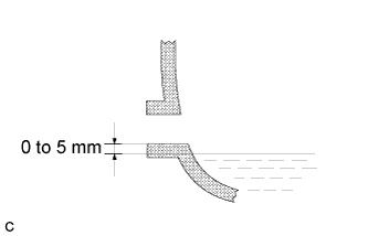
Check that the oil surface is within 5 mm (0.20 in.) of the lowest position of the inner surface of the differential filler plug opening.
Note
-
Excessively large or small amounts of oil may cause trouble.
-
After replacing oil, drive the vehicle and check the oil level.
Tech Tips
If necessary, fill the rear differential carrier with hypoid gear oil.
Oil grade Hypoid gear oil API GL-5 Recommended oil viscosity Above -18°C (0°F) : SAE 90 Below -18°C (0°F) : SAE 80W or 80W-90 Capacity 0.9 +/- 0.05 liters (0.95 +/- 0.05 US qts, 0.79 +/- 0.04 lmp. qts) -
-
Check for oil leakage when the oil level is low.
-
Install the differential filler plug and a new gasket.
- Torque:
- 49 N*m { 500 kgf*cm, 36 ft.*lbf }
-
-
INSTALL REAR DIFFERENTIAL FILLER PLUG
-
Using a hexagon wrench (10 mm), install the filler plug with a new gasket.
- Torque:
- 49 N*m { 500 kgf*cm, 36 ft.*lbf }
-
-
INSTALL REAR WHEEL
- Torque:
- 103 N*m { 1050 kgf*cm, 76 ft.*lbf }
-
INSPECT REAR WHEEL ALIGNMENT
-
CHECK FOR REAR SPEED SENSOR SIGNAL