DIFFERENTIAL OIL SEAL REPLACEMENT
-
REMOVE ENGINE UNDER COVER ASSEMBLY
-

Remove the 2 bolts and engine under cover assembly RR.
-

Remove the 2 bolts, 2 screws, 5 clips and engine under cover assembly.
-
-
REMOVE NO. 1 ENGINE UNDER COVER
-
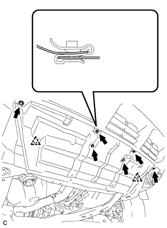
Remove the 6 bolts, 2 clips and No. 1 engine under cover.
-
-
REMOVE NO. 2 ENGINE UNDER COVER
-
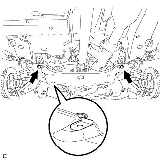
Remove the 2 bolts and No. 2 engine under cover.
-
-
DRAIN AUTOMATIC TRANSAXLE FLUID
-
Remove the drain plug and gasket, and drain ATF.
-
Install a new gasket and the drain plug.
- Torque:
- 49 N*m { 500 kgf*cm, 36 ft.*lbf }
-
-
REMOVE FRONT WHEEL
-
REMOVE FRONT AXLE HUB NUT LH
-
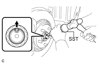
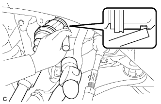
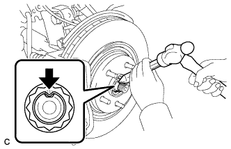
Using SST and a hammer, release the staked part of the front axle hub nut.
- SST
- 09930-00010
Note
Loosen the staked part of the nut completely, otherwise the threads of the drive shaft may be damaged.
-
While applying the brakes, remove the front axle hub nut.
-
-
SEPARATE FRONT STABILIZER LINK ASSEMBLY LH
-
Remove the nut and separate the front stabilizer link assembly from the front shock absorber.
Tech Tips
If the ball joint turns together with the nut, use a hexagon wrench (6 mm) to hold the stud.
-
-
SEPARATE FRONT SPEED SENSOR LH
-
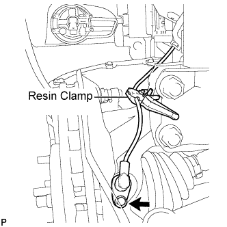
Remove the bolt and resin clamp, and separate the front speed sensor.
-
-
SEPARATE TIE ROD ASSEMBLY LH
-
Remove the cotter pin and the nut.
-
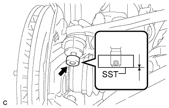
Install SST to the tie rod end.
- SST
- 09960-20010 ( 09961-02060 )
Note
Make sure that the upper ends of the tie rod end and SST are aligned.
-
Using SST, separate the tie rod end from the steering knuckle.
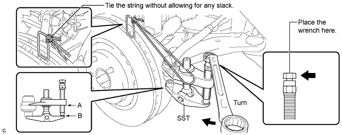
- SST
- 09960-20010 ( 09961-02010 )
Note
-
When securing SST to the steering knuckle, be sure to tighten the string of SST to prevent it from falling.
-
Install SST so that A and B are parallel.
-
Be sure to place the wrench on the part indicated in the illustration.
-
Do not damage the front disc brake dust cover.
-
Do not damage the ball joint dust cover.
-
Do not damage the steering knuckle.
-
-
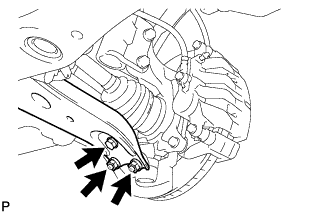
SEPARATE NO. 1 FRONT SUSPENSION LOWER ARM LH
-
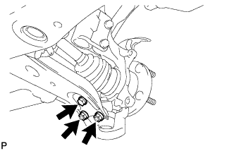
Remove the bolt and 2 nuts, and separate the front lower suspension arm from the front lower ball joint.
-
-
SEPARATE FRONT AXLE ASSEMBLY LH
-
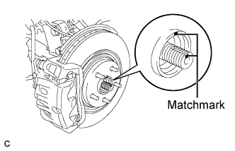
Put matchmarks on the front drive shaft assembly and the front axle hub sub-assembly.
Note
Do not punch the marks.
-
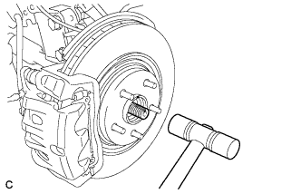
Using a plastic hammer, separate the front drive shaft assembly from the front axle assembly.
Note
Be careful not to damage the drive shaft boot and speed sensor rotor.
-
-
REMOVE FRONT DRIVE SHAFT ASSEMBLY LH
-
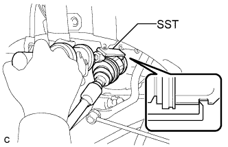
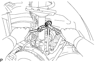
Using SST, remove the front drive shaft assembly LH.
- SST
- 09520-01010
- 09520-24010 ( 09520-32040 )
Note
-
Be careful not to damage the drive shaft dust cover, boot, or oil seal.
-
Be careful not to drop the drive shaft assembly.
-
-
SECURE FRONT AXLE HUB SUB-ASSEMBLY LH
-
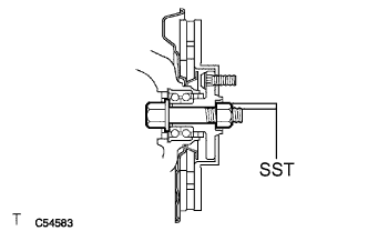
Using SST, secure the front axle hub bearing.
- SST
- 09608-16042 ( 09608-02021, 09608-02041 )
Note
The hub bearing may be damaged if it is subjected to the vehicle's full weight, such as when moving the vehicle with the drive shaft removed. If it is necessary to place the vehicle's weight on the hub bearing, first support it with SST.
-
-
REMOVE DIFFERENTIAL SIDE BEARING RETAINER OIL SEAL
-
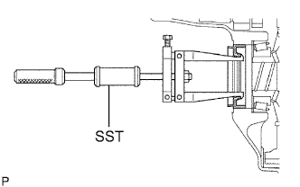
Using SST, pull out the oil seal.
- SST
- 09308-00010
-
-
INSTALL DIFFERENTIAL SIDE BEARING RETAINER OIL SEAL
-
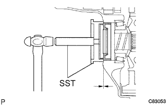
Coat the lip of a new oil seal with MP grease.
-
Using SST and a hammer, install a new oil seal.
- SST
- 09223-15020
- 09950-70010 ( 09951-07150 )
Oil seal installation depth -0.5 to 0.2 mm (-0.020 to 0.008 in.)
-
-
INSTALL FRONT DRIVE SHAFT ASSEMBLY LH
-
Align the shaft splines and install the drive shaft assembly LH with a brass bar and hammer.
Note
-
Set the shaft snap ring with the opening facing down.
-
Be careful not to damage the drive shaft dust cover, boot, or oil seal.
-
Move the drive shaft assembly while keeping it level.
-
-
-
INSTALL FRONT AXLE ASSEMBLY LH
-
Align the matchmarks and install the front drive shaft assembly to the front axle hub sub-assembly.
-
-
INSTALL NO. 1 FRONT SUSPENSION LOWER ARM LH
-
Install the No. 1 front suspension lower arm to the front lower ball joint with the bolt and 2 nuts.
- Torque:
- 92 N*m { 938 kgf*cm, 68 ft.*lbf }
-
-
INSTALL TIE ROD ASSEMBLY LH
-
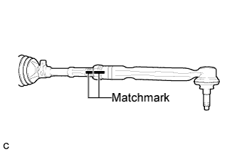
Install the lock nut and the tie rod assembly LH to the steering rack end sub-assembly until the matchmarks are aligned.
Tech Tips
After adjusting toe-in, torque the lock nut.
-
-
INSTALL FRONT SPEED SENSOR LH
-
Install the resin clamp and front speed sensor with the bolt.
- Torque:
- 8.0 N*m { 82 kgf*cm, 71 in.*lbf }
Note
-
Prevent foreign matter from attaching to the sensor tip.
-
Firmly insert the sensor body into the knuckle before tightening the bolt.
-
After installing the sensor to the knuckle, make sure that there is no clearance between the sensor stay and knuckle. Also make sure that no foreign matter is stuck between the parts.
-
To prevent interference between the sensor and magnetic rotor, do not rotate the sensor body during or after the insertion of the sensor body to the knuckle.
-
-
INSTALL FRONT STABILIZER LINK ASSEMBLY LH
-
Install the front stabilizer link assembly to the front shock absorber with the nut.
- Torque:
- 74 N*m { 755 kgf*cm, 55 ft.*lbf }
Note
If the ball joint turns together with the nut, use a hexagon wrench (6 mm) to hold the stud bolt.
-
-
INSTALL FRONT AXLE HUB NUT LH
-
Clean the threaded parts on the drive shaft and axle hub nut using a non-residue solvent.
Tech Tips
-
Be sure to perform this work for a new drive shaft.
-
Keep the threaded parts free of oil and foreign objects.
-
-
Using a socket wrench (30 mm), install a new axle hub nut.
- Torque:
- 294 N*m { 2996 kgf*cm, 216 ft.*lbf }
-
Using a chisel and hammer, stake the front axle hub nut.
-
-
INSTALL FRONT WHEEL
- Torque:
- 103 N*m { 1050 kgf*cm, 76 ft.*lbf }
-
ADD AUTOMATIC TRANSAXLE FLUID
-
INSPECT AUTOMATIC TRANSAXLE FLUID
Tech Tips
Drive the vehicle so that the engine and transaxle are at normal operating temperature.
Fluid temperature 70 to 80°C (158 to 176°F)
-
Park the vehicle on a level surface and set the parking brake.
-
With the engine idling and the brake pedal depressed, move the shift lever to all positions from P to S1 and return to the P position.
-
Take out the dipstick and wipe it clean.
-
Put the dipstick back all the way.
-
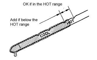
Take out the dipstick again and check that the fluid level is within the HOT range.
If the fluid level is below the HOT range, add new fluid and recheck the fluid level.
If the fluid level exceeds the HOT range, drain the fluid once, add the proper amount of new fluid and recheck the fluid level.
If there are leaks, it is necessary to repair or replace O-rings, FIPGs, oil seals, plugs and/or other parts.
-
-
INSTALL NO. 2 ENGINE UNDER COVER
-
Install the No. 2 engine under cover with the 2 bolts.
-
-
INSTALL NO. 1 ENGINE UNDER COVER
-
Install the No. 1 engine under cover with the 6 bolts and 2 clips.
-
-
INSTALL ENGINE UNDER COVER ASSEMBLY
-
Install the engine under cover assembly with the 2 bolts, 2 screws and 5 clips.
-
Install the engine under cover assembly RR with the 2 bolts.
-
-
INSTALL FRONT WHEEL ALIGNMENT
Tech Tips
-
INSTALL ABS SPEED SENSOR SIGNAL
Tech Tips
-
REMOVE AUTOMATIC TRANSAXLE ASSEMBLY
Tech Tips
-
REMOVE NO. 1 TRANSFER CASE PLUG
-
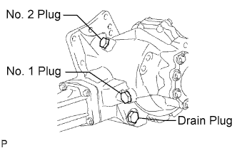
Remove the No. 1 transfer case plug.
-
Remove the No. 1 gasket from the No. 1 transfer case plug.
-
-
REMOVE NO. 2 TRANSFER CASE PLUG
-
Remove the No. 2 transfer case plug.
-
Remove the No. 2 gasket from the No. 2 transfer case plug.
-
-
REMOVE TRANSFER DRAIN PLUG
-
Remove the transfer drain plug and bleed the oil.
-
Remove the drain gasket from the transfer drain plug.
-
-
REMOVE TRANSFER ASSEMBLY
-
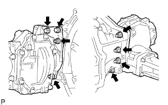
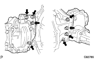
Remove the 2 bolts and 6 nuts.
-
Using a plastic hammer, remove the transfer assembly from the transaxle assembly.
Note
-
Remove the transfer assembly from the transaxle assembly without tilting it.
-
When removing the transfer assembly, do not hold onto the oil seal parts on both sides of the assembly.
-
-
-
REMOVE TRANSAXLE HOUSING OIL SEAL
- SST
- 09308-00010
-
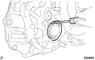
Using a screwdriver with vinyl tape wrapped around its tip, remove the oil seal.
Note
Be careful not to damage the housing.
-
INSTALL TRANSAXLE HOUSING OIL SEAL
-
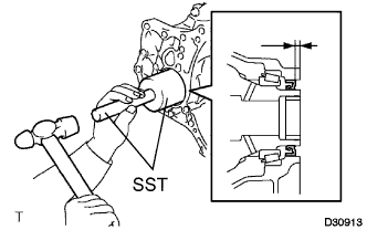
Coat the lip of a new oil seal with MP grease.
-
Using SST and a hammer, install a new oil seal.
- SST
- 09649-17010
- 09950-70010 ( 09951-07200 )
Oil seal installation depth 5.5 to 6.5 mm (0.217 to 0.256 in.)
-
-
INSTALL TRANSFER ASSEMBLY
-
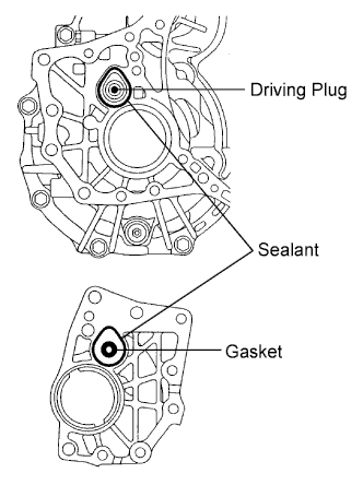
Apply sealant 1281 to the transaxle assembly and transfer assembly in a continuous bead of 1.2 mm diameter as shown in the illustration.
Note
-
Wipe any grease off from the attaching surfaces.
-
Install it within 10 minutes after applying the sealant.
-
Sealant stuck on the gasket, case oil seal and driving plug may cause oil leakage and seizure due to oil shortage. Care must be taken.
-
-
Install the transfer assembly to the transaxle assembly with the 2 bolts and 6 nuts.
- Torque:
- 69 N*m { 700 kgf*cm, 51 ft.*lbf }
Note
-
Check that the gasket is installed to the transfer assembly before installing them to the transaxle assembly.
-
Install the transfer assembly to the transaxle assembly without tilting.
-
When moving the transfer assembly, do not hold the oil seal on the both sides.
-
-
INSTALL AUTOMATIC TRANSAXLE ASSEMBLY
Tech Tips