COOLING FAN SYSTEM Cooling Fan Circuit
DESCRIPTION
The ECM calculates an appropriate cooling fan speed based on the engine coolant temperature, air conditioning switch condition, refrigerant pressure, engine speed, and vehicle speed and sends the signals to the cooling fan ECU to regulate the cooling fan. The cooling fan ECU controls the cooling fan speed based on the duty ratio signal sent from the ECM. By basing its control on the operating conditions, the ECM can control the fan speed optimally using the cooling fan ECU, achieving both high cooling performance and quietness. The cooling fan speed is determined based on engine coolant temperature, air conditioner operating conditions, engine speed, and vehicle speed.
INSPECTION PROCEDURE
PROCEDURE
-
PERFORM ACTIVE TEST USING INTELLIGENT TESTER (CONTROL THE COOLING FAN)
-
Connect the intelligent tester to the DLC3.
-
Turn the ignition switch on (IG).
-
Enter the following menus: Powertrain / Engine and ECT / Active Test / Control the Cooling Fan.
-
Check the operation of the cooling fan while operating it using the intelligent tester.
OK The cooling fan rotates.
NG 
CHECK HARNESS AND CONNECTOR (ECM - COOLING FAN ECU) Click here
OK 
REPLACE ECM Click here
-
-
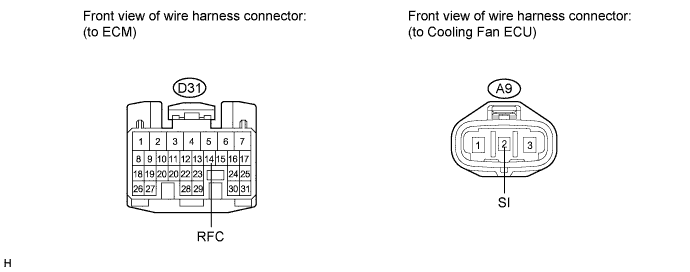
CHECK HARNESS AND CONNECTOR (ECM - COOLING FAN ECU)
-
Disconnect the D31 connector from the ECM.
-
Disconnect the cooling fan ECU connector.
-
Measure the resistance according to the value(s) in the table below.
Standard resistance Tester Connection Condition Specified Condition D31-14 (RFC) - A9-2 (SI) Always Below 1 Ω
NG 
REPAIR OR REPLACE HARNESS OR CONNECTOR
OK 
-
-
INSPECT NO. 1 COOLING FAN MOTOR
-
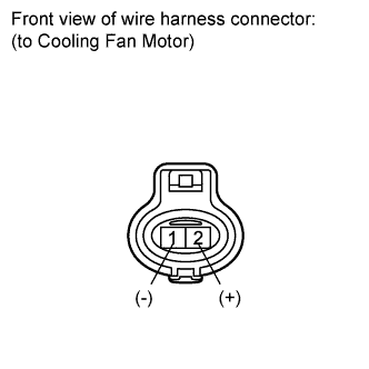
Disconnect the No. 1 cooling fan motor connector.
-
Connect the battery positive terminal to terminal 2 of the cooling fan connector, and connect the battery negative terminal to terminal 1 of the No. 1 cooling fan motor connector.
OK The No. 1 cooling fan rotates.
NG
REPLACE NO. 1 COOLING FAN MOTOR Click here
OK
-
-
INSPECT NO. 2 COOLING FAN MOTOR
-
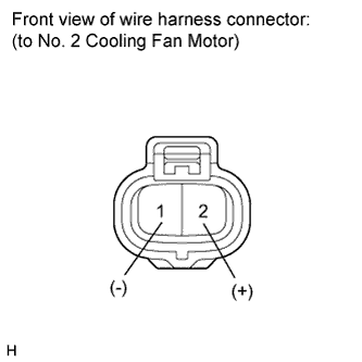
Disconnect the No. 2 cooling fan motor connector.
-
Connect the battery positive terminal to terminal 2 of the cooling fan connector, and connect the battery negative terminal to terminal 1 of the No. 2 cooling fan motor connector.
OK The No. 2 cooling fan rotates.
NG
REPLACE NO. 2 COOLING FAN MOTOR Click here
OK
-
-
CHECK COOLING FAN ECU (POWER SOURCE)
-
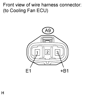
Disconnect the cooling fan ECU connector.
-
Turn the ignition switch on (IG).
-
Measure the voltage according to the value(s) in the table below.
Standard voltage Tester Connection Switch Condition Specified Condition A9-3 (+B1) - A9-1 (E1) Ignition switch on (IG) 11 to 14 V
NG
CHECK HARNESS AND CONNECTOR (COOLING FAN ECU - BODY GROUND) Click here
OK
REPLACE COOLING FAN ECU Click here
-
-
CHECK HARNESS AND CONNECTOR (COOLING FAN ECU - BODY GROUND)
-
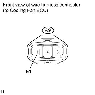
Disconnect the cooling fan ECU connector.
-
Measure the resistance according to the value(s) in the table below.
Standard resistance Tester Connection Condition Specified Condition A9-1 (E1) - Body ground Always Below 1 Ω
NG
REPAIR OR REPLACE HARNESS OR CONNECTOR
OK
-
-
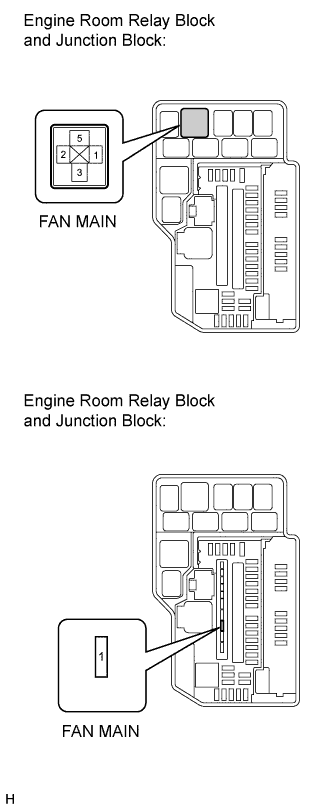
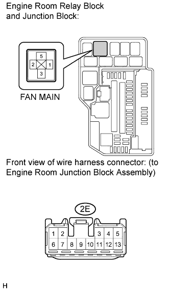
INSPECT FAN MAIN RELAY
-
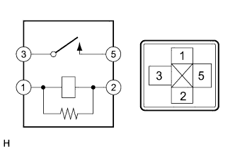
Remove the FAN MAIN relay from the engine room relay block and junction block.
-
Measure the resistance according to the value(s) in the table below.
Standard resistance Tester Connection Condition Specified Condition 3 - 5 Battery voltage is not applied between terminals 1 and 2 10 kΩ or higher 3 - 5 Apply battery voltage between terminals 1 and 2 Below 1 Ω
NG
REPLACE FAN MAIN RELAY
OK
-
-
CHECK HARNESS AND CONNECTOR (COOLING FAN ECU - FAN MAIN RELAY)
-
Disconnect the cooling fan ECU connector.
-
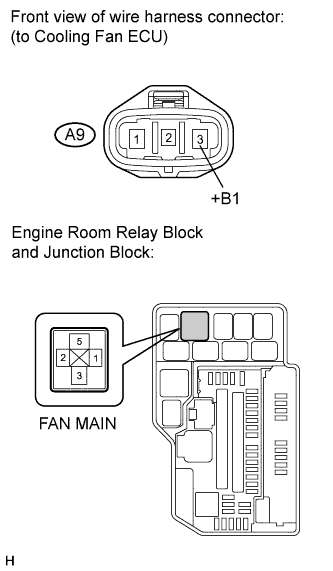
Remove the FAN MAIN relay from the engine room relay block and junction block.
-
Measure the resistance according to the value(s) in the table below.
Standard resistance Tester Connection Condition Specified Condition A9-3 (+B1) - 5 (FAN MAIN relay) Always Below 1 Ω
NG
REPAIR OR REPLACE HARNESS OR CONNECTOR
OK
-
-
CHECK HARNESS AND CONNECTOR (FAN MAIN RELAY - BODY GROUND)
-
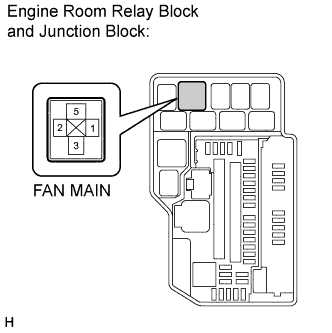
Remove the FAN MAIN relay from the engine room relay block and junction block.
-
Measure the resistance according to the value(s) in the table below.
Standard resistance Tester Connection Condition Specified Condition 2 (FAN MAIN relay) - Body ground Always Below 1 Ω
NG
REPAIR OR REPLACE HARNESS OR CONNECTOR
OK
-
-
CHECK HARNESS AND CONNECTOR (FAN MAIN RELAY - FAN MAIN FUSE)
-
Remove the FAN MAIN relay from the engine room relay block and junction block.
-
Remove the fusible link block assembly from the engine room relay block and junction block.
-
Measure the resistance according to the value(s) in the table below.
Standard resistance Tester Connection Condition Specified Condition 3 (FAN MAIN relay) - 1 (FAN MAIN fuse) Always Below 1 Ω
NG
REPAIR OR REPLACE HARNESS OR CONNECTOR
OK
-
-
INSPECT FUSIBLE LINK BLOCK ASSEMBLY (FAN MAIN FUSE)
-
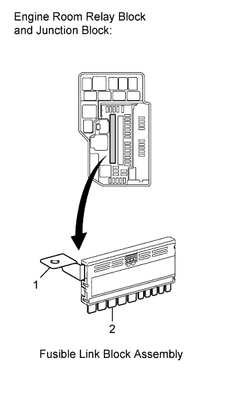
Remove the fusible link block assembly from the engine room relay block and junction block.
-
Measure the resistance according to the value(s) in the table below.
Standard resistance Tester Connection Condition Specified Condition 1 - 2 (FAN MAIN fuse) Always Below 1 Ω
NG
REPLACE FUSIBLE LINK BLOCK ASSEMBLY
OK
-
-
CHECK FUSE (EFI MAIN)
-
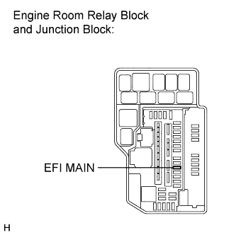
Remove the EFI MAIN fuse from the engine room relay block and junction block.
-
Measure the resistance according to the value(s) in the table below.
Standard resistance Tester Connection Condition Specified Condition EFI MAIN fuse Always Below 1 Ω
-
NG
REPLACE FUSE
OK
-
-
CHECK HARNESS AND CONNECTOR (EFI MAIN FUSE - ENGINE ROOM JUNCTION BLOCK ASSEMBLY)
-
Remove the EFI MAIN fuse from the engine room relay block and junction block.
-
Remove the engine room junction block assembly from the engine room relay block and junction block.
-
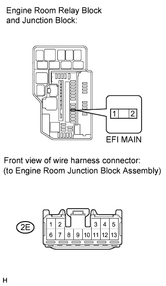
Disconnect the 2E connector from the engine room junction block assembly.
-
Measure the resistance according to the value(s) in the table below.
Standard resistance Tester Connection Condition Specified Condition 2 (EFI MAIN fuse) - 2E-12 Always Below 1 Ω
NG
REPAIR OR REPLACE HARNESS OR CONNECTOR
OK
-
-
CHECK HARNESS AND CONNECTOR (FAN MAIN RELAY - ENGINE ROOM JUNCTION BLOCK ASSEMBLY)
-
Remove the FAN MAIN relay from the engine room relay block and junction block.
-
Remove the engine room junction block assembly from the engine room relay block and junction block.
-
Disconnect the 2E connector from the engine room junction block assembly.
-
Measure the resistance according to the value(s) in the table below.
Standard resistance Tester Connection Condition Specified Condition 1 (FAN MAIN reray) - 2E-7 Always Below 1 Ω
NG
REPAIR OR REPLACE HARNESS OR CONNECTOR
OK
-
-
CHECK HARNESS AND CONNECTOR (ENGINE ROOM JUNCTION BLOCK ASSEMBLY - BODY GROUND)
-
Remove the engine room junction block assembly from the engine room relay block and junction block.
-
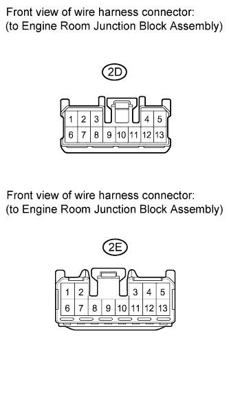
Disconnect the 2D and 2E connectors from the engine room junction block assembly.
-
Measure the resistance according to the value(s) in the table below.
Standard resistance Tester Connection Condition Specified Condition 2D-8 - Body ground Always Below 1 Ω 2E-10 - Body ground Always Below 1 Ω
NG
REPAIR OR REPLACE HARNESS OR CONNECTOR
OK
-
-
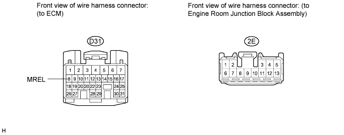
CHECK HARNESS AND CONNECTOR (ECM - ENGINE ROOM JUNCTION BLOCK ASSEMBLY)
-
Disconnect the D31 connector from the ECM.
-
Remove the engine room junction block assembly from the engine room relay block and junction block.
-
Disconnect the 2E connector from the engine room junction block assembly.
-
Measure the resistance according to the value(s) in the table below.
Standard resistance Tester Connection Condition Specified Condition D31-8 (MREL) - 2E-9 Always Below 1 Ω
NG
REPAIR OR REPLACE HARNESS OR CONNECTOR
OK
-
-
INSPECT ENGINE ROOM JUNCTION BLOCK ASSEMBLY (EFI RELAY)
-
Remove the engine room junction block assembly from the engine room relay block and junction block.
-
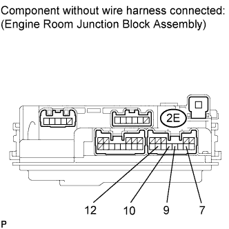
Measure the resistance according to the value(s) in the table below.
Standard resistance Tester Connection Condition Specified Condition 2E-12 - 2E-7 Battery voltage is not applied between terminals 2E-9 and 2E-10 10 kΩ or higher 2E-12 - 2E-7 Apply battery voltage between terminals 2E-9 and 2E-10 Below 1 Ω Note
While using the battery for the inspection, do not bring the positive and negative tester probes too close to each other as a short circuit may occur.
NG
REPLACE ENGINE ROOM JUNCTION BLOCK ASSEMBLY Click here
OK
REPLACE ECM Click here
-