FUEL TANK INSTALLATION
-
INSTALL FUEL TANK CUSHION SET
-
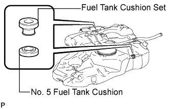
Install the 2 fuel tank cushion sets and 2 No. 5 fuel tank cushions.
-
-
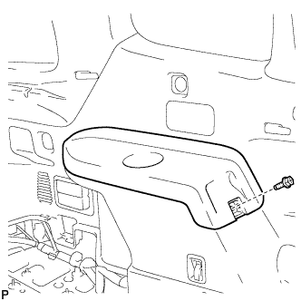
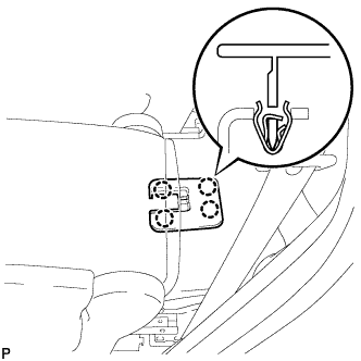
INSTALL FUEL TANK SIDE PLATE
-
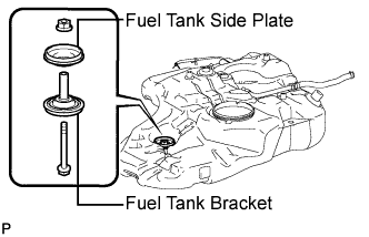
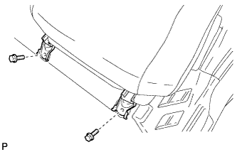
Install the fuel tank side plate and fuel tank bracket with the bolt and nut.
- Torque:
- 30 N*m { 306 kgf*cm, 22 ft.*lbf }
Tech Tips
While keeping the bolt from rotating, tighten the nut.
-
-
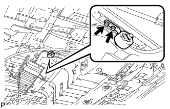
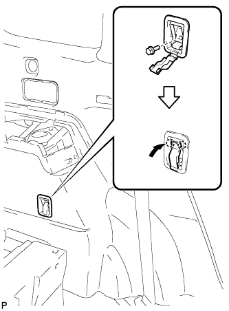
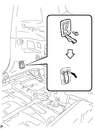
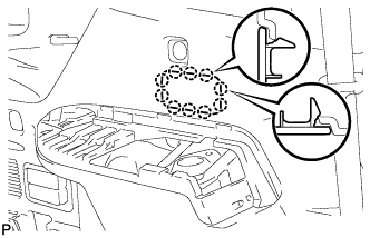
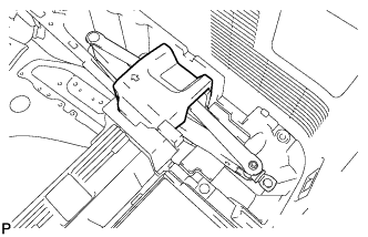
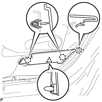
INSTALL TANK SUCTION TUBE SUPPORT
-
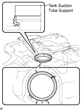
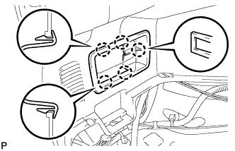
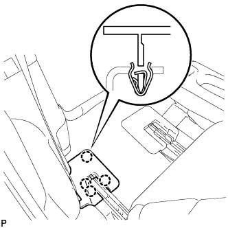
Install a new tank suction tube support as shown in the illustration.
Tech Tips
Align the protrusions of the tank suction tube support with the notches of the fuel tank assembly.
-
-
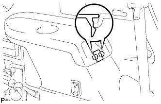
INSTALL FUEL TANK TO FILLER PIPE HOSE
-
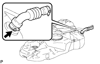
Install the fuel tank to filler pipe hose with the hose clamp.
-
-
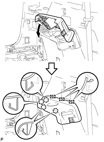
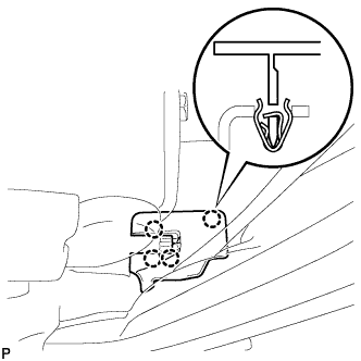
INSTALL FUEL PUMP TUBE SUB-ASSEMBLY
-
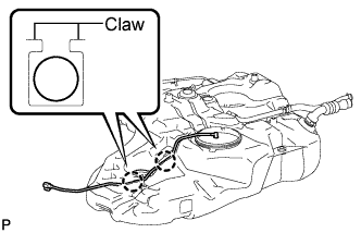
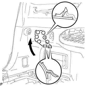
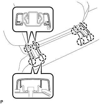
Engage the 2 claws to install the fuel pump tube sub-assembly.
-
-
INSTALL NO. 1 FUEL TANK CUSHION
-
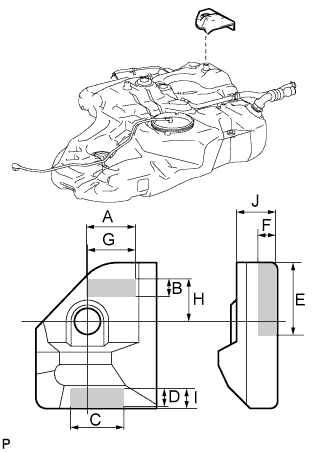
Apply new butyl tape to the No. 1 fuel tank cushion as shown in the illustration.
Length Dimension Length A 55 mm (2.17 in.) B 20 mm (0.79 in.) C 60 mm (2.36 in.) D 20 mm (0.79 in.) E 80 mm (3.15 in.) F 20 mm (0.79 in.) G 53.4 mm (2.10 in.) H 49.2 mm (1.94 in.) I 18.9 mm (0.74 in.) J 43.3 mm (1.70 in.) -
Install the No. 1 fuel tank cushion.
-
-
INSTALL REAR FUEL TANK SIDE PLATE
-
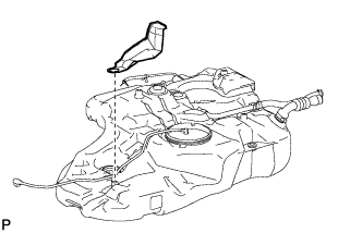
Install the rear fuel tank side plate.
-
-
INSTALL FUEL TANK ASSEMBLY
-
Set the fuel tank onto a transmission jack.
-
Using the transmission jack, install the fuel tank.
-
Tighten the 2 nuts.
- Torque:
- 20 N*m { 200 kgf*cm, 14 ft.*lbf }
-
Install the fuel tank band sub-assembly LH and RH with the 4 bolts.
- Torque:
- 45 N*m { 459 kgf*cm, 33 ft.*lbf }
-
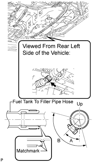
Align the matchmarks and install the fuel tank to filler pipe hose to the filler pipe.
-
Install the hose clamp within the range shown in the illustration.
Tech Tips
-
A = 45°
-
B = 120°
-
-
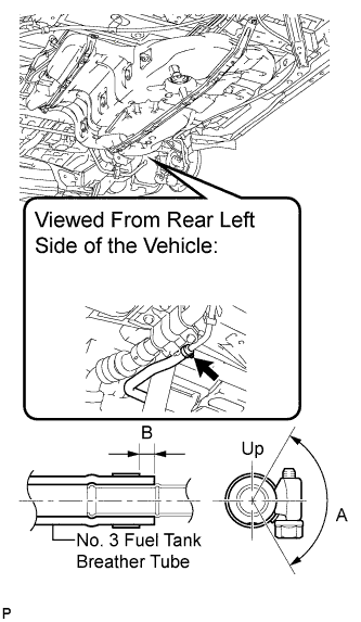
Connect the No. 3 fuel tank breather tube.
-
Install the hose clamp within the range shown in the illustration.
Tech Tips
-
A = 120°
-
B = 2 to 7 mm (0.079 to 0.276 in.)
-
-
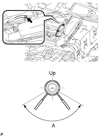
Connect the fuel tank vent hose.
-
Install the clip within the range shown in the illustration.
Tech Tips
A= 120°
-
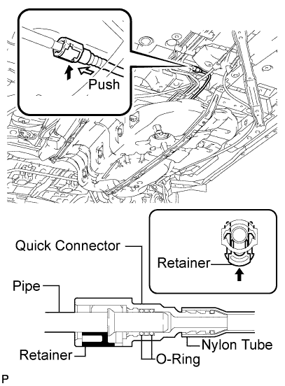
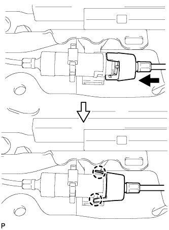
Connect the fuel pump tube.
-
Push in the quick connector to the fuel pipe and push in the retainer to lock the claws.
Note
-
Check if there is any damage or foreign matter on the connecting parts.
-
After connecting, check if the quick connector and the pipe are securely connected by pulling on them.
-
-
-
-
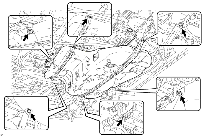
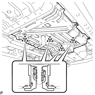
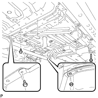
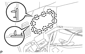
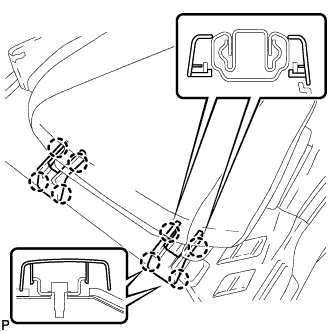
INSTALL NO. 1 FUEL TANK PROTECTOR SUB-ASSEMBLY
-
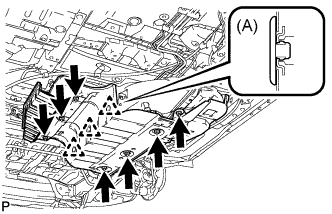
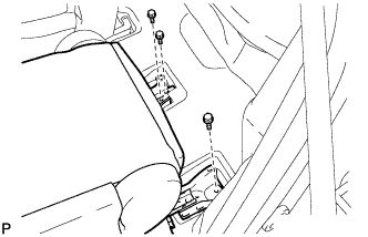
Install the No. 1 fuel tank protector sub-assembly with the 7 nuts.
- Torque:
- 5.5 N*m { 56 kgf*cm, 49 in.*lbf }
-
Install 3 new clips (A).
-
-
TEMPORARILY INSTALL REAR SUSPENSION MEMBER (for 4WD)
-
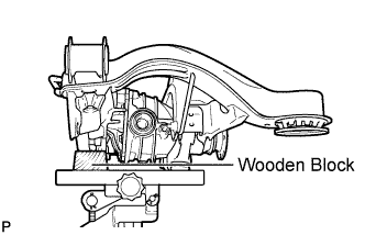
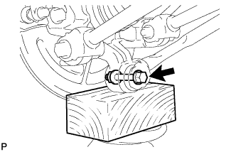
Support the rear suspension member with a jack using a wooden block.
Tech Tips
-
Use a properly sized wooden block to keep the jack and suspension member level.
-
Support the rear suspension member until retightening of the suspension member is complete.
-
-
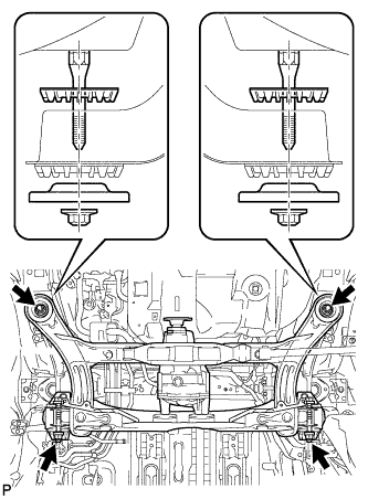
Raise the rear suspension member with a jack.
-
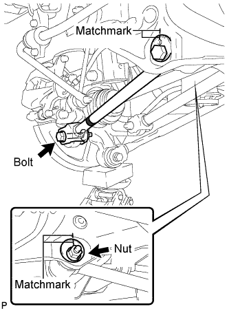
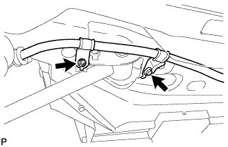
Temporarily install the rear suspension member, the 2 rear upper suspension member stoppers and rear lower suspension member stopper retainers with the 4 nuts and the 2 bolts.
-
Fully tighten the 2 nuts.
- Torque:
- 115 N*m { 1170 kgf*cm, 85 ft.*lbf }
-
-
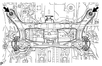
FULLY TIGHTEN REAR SUSPENSION MEMBER (for 4WD)
-
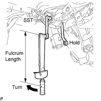
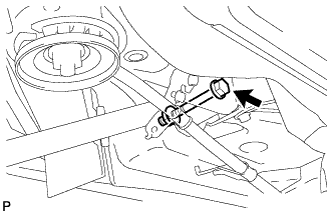
Using SST and a socket wrench (19 mm), fully tighten the nut (LH side).
- Torque:
- without SST
- 181 N*m { 1850 kgf*cm, 133 ft.*lbf }
- with SST
- 134 N*m { 1366 kgf*cm, 98 ft.*lbf }
- SST
- 09961-00950
Note
-
Use a torque wrench with a fulcrum length of 425 mm (16.73 in.).
-
This torque value is effective when SST is parallel to the torque wrench.
-
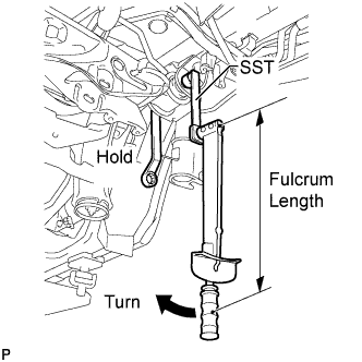
Using SST and a socket wrench (19 mm), fully tighten the nut (RH side).
- Torque:
- without SST
- 181 N*m { 1850 kgf*cm, 133 ft.*lbf }
- with SST
- 134 N*m { 1366 kgf*cm, 98 ft.*lbf }
- SST
- 09961-00950
Note
-
Use a torque wrench with a fulcrum length of 425 mm (16.73 in.).
-
This torque value is effective when SST is parallel to the torque wrench.
-
-
INSTALL REAR DRIVE SHAFT SNAP RING LH (for 4WD)
-
Install a new rear drive shaft snap ring.
-
-
INSTALL REAR DRIVE SHAFT ASSEMBLY LH (for 4WD)
-
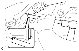
Align the shaft splines and install the rear drive shaft assembly with a brass bar and hammer.
Note
-
Set the snap ring with the opening facing downward.
-
Be careful not to damage the oil seal, boot, or dust cover.
-
Install the drive shaft assembly while keeping it level.
-
-
-
INSTALL REAR DRIVE SHAFT SNAP RING RH (for 4WD)
Tech Tips
Perform the same procedure as the LH side.
-
INSTALL REAR DRIVE SHAFT ASSEMBLY RH (for 4WD)
Tech Tips
Perform the same procedure as the LH side.
-
INSTALL REAR DIFFERENTIAL DRAIN PLUG (for 4WD)
-
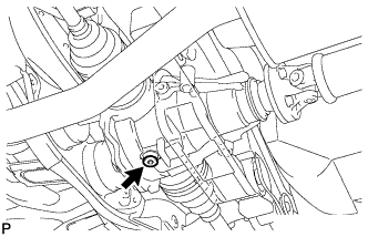
Using a hexagon wrench (10 mm), install the filler plug with a new gasket.
- Torque:
- 49 N*m { 500 kgf*cm, 36 ft.*lbf }
-
-
ADD DIFFERENTIAL OIL (for 4WD)
-
Fill the rear differential carrier assembly with hypoid gear oil.
-
-
INSPECT DIFFERENTIAL OIL (for 4WD)
-
Stop the vehicle on a level place.
-
Remove the differential filler plug and gasket.
-
Check that the oil surface is within 5 mm (0.20 in.) of the lowest position of the inner surface of the differential filler plug opening.
Note
-
Excessively large or small amounts of oil may cause trouble.
-
After replacing oil, drive the vehicle and check the oil level.
Tech Tips
If necessary, fill the rear differential carrier with hypoid gear oil.
Oil grade Hypoid gear oil API GL-5 Recommended oil viscosity Above -18°C (0°F) : SAE 90 Below -18°C (0°F) : SAE 80W or 80W-90 Capacity 0.9 +/- 0.05 liters (0.95 +/- 0.05 US qts, 0.79 +/- 0.04 lmp. qts) -
-
Check for oil leakage when the oil level is low.
-
Install the differential filler plug and a new gasket.
- Torque:
- 49 N*m { 500 kgf*cm, 36 ft.*lbf }
-
-
INSTALL REAR DIFFERENTIAL FILLER PLUG (for 4WD)
-
Using a hexagon wrench (10 mm), install the filler plug with a new gasket.
- Torque:
- 49 N*m { 500 kgf*cm, 36 ft.*lbf }
-
-
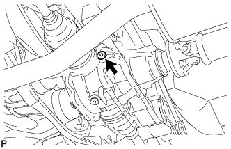
TEMPORARILY INSTALL REAR NO. 1 SUSPENSION ARM ASSEMBLY RH (for 4WD)
-
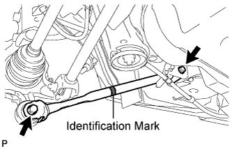
Temporarily install the rear No. 1 suspension arm assembly RH to the rear suspension member sub-assembly with the bolt and the nut.
Note
-
Ensure that the identification mark faces the rear side of the vehicle.
-
Since a stopper nut is used, temporarily tighten the bolt.
-
-
-
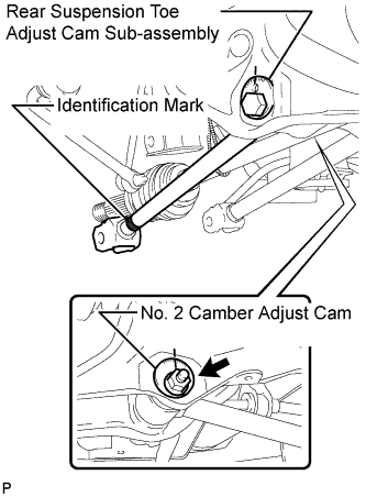
TEMPORARILY INSTALL REAR NO. 2 SUSPENSION ARM ASSEMBLY LH (for 4WD)
-
Temporarily install the rear No. 2 suspension arm assembly LH to the rear suspension member sub-assembly with the rear suspension toe adjust cam sub-assembly, the No. 2 camber adjust cam and the nut.
Note
Ensure that the identification mark faces the rear side of the vehicle.
Tech Tips
When temporarily tightening the nut, keep the rear suspension toe adjust cam sub-assembly from rotating.
-
-
TEMPORARILY INSTALL REAR NO. 2 SUSPENSION ARM ASSEMBLY RH (for 4WD)
Tech Tips
Perform the same procedure as the LH side.
-
INSTALL REAR AXLE CARRIER SUB-ASSEMBLY LH (for 4WD)
-
Temporarily install the the rear axle carrier sub-assembly with the 2 bolts and the 2 nuts.
Note
-
Be careful not to damage the outboard joint boot.
-
Be careful not to damage the speed sensor rotor.
-
Prevent foreign matter from adhering to the speed sensor rotor.
-
-
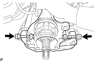
Install the rear axle carrier sub-assembly with the 2 bolts and the 2 nuts.
- Torque:
- 290 N*m { 2956 kgf*cm, 213 ft.*lbf }
Note
-
Be careful not to damage the outboard joint boot.
-
Be careful not to damage the speed sensor rotor.
-
Prevent foreign matter from adhering to the speed sensor rotor.
-
Do not rotate the drive shaft with the rear axle hub and bearing assembly removed.
Tech Tips
Insert the bolts from the rear side.
-
-
INSTALL REAR AXLE CARRIER SUB-ASSEMBLY RH (for 4WD)
Tech Tips
Perform the same procedure as the LH side.
-
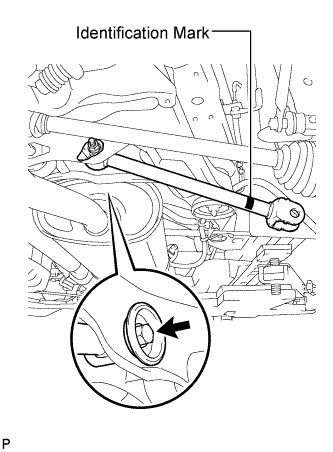
TEMPORARILY INSTALL REAR STRUT ROD ASSEMBLY LH (for 4WD)
-
Check that the identification mark of the rear strut rod assembly is positioned on the inner side of the vehicle.
-
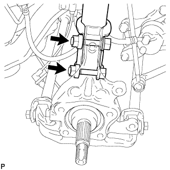
Temporarily install the rear strut rod assembly with the 2 bolts and the 2 nuts.
Note
Since stopper nuts are used, temporarily tighten the bolts.
-
-
TEMPORARILY INSTALL REAR STRUT ROD ASSEMBLY RH (for 4WD)
Tech Tips
Perform the same procedure as the LH side.
-
INSTALL REAR AXLE HUB AND BEARING ASSEMBLY LH (for 4WD)
-
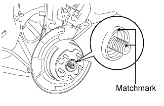
Align the matchmarks on the drive shaft and rear axle hub.
Note
Do not rotate the drive shaft.
-
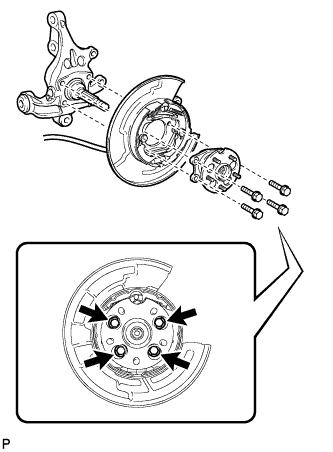
Install the parking brake assembly and the rear axle hub and bearing assembly with the 4 bolts.
- Torque:
- 75 N*m { 764 kgf*cm, 55 ft.*lbf }
Note
Do not twist the No. 3 parking brake cable assembly when installing it.
-
-
INSTALL REAR AXLE HUB AND BEARING ASSEMBLY RH (for 4WD)
Tech Tips
Perform the same procedure as the LH side.
-
INSTALL REAR DISC (for 4WD LH Side)
-
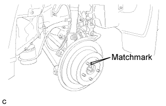
Align matchmarks and install the rear disc.
Note
When replacing the rear disc with a new one, select the installation position where the rear disc has minimal runout.
-
-
INSTALL REAR DISC (for 4WD RH Side)
Tech Tips
Perform the same procedure as the LH side.
-
INSTALL REAR DISC BRAKE CALIPER ASSEMBLY LH (for 4WD)
-
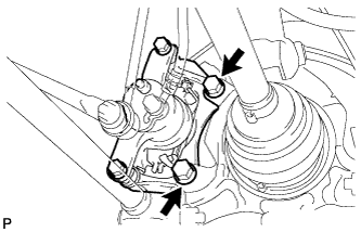
Install the rear disc brake caliper assembly with the 2 bolts.
- Torque:
- 78 N*m { 795 kgf*cm, 57 ft.*lbf }
-
-
INSTALL REAR DISC BRAKE CALIPER ASSEMBLY RH (for 4WD)
Tech Tips
Perform the same procedure as the LH side.
-
TEMPORARILY INSTALL REAR AXLE SHAFT NUT LH (for 4WD)
-
Clean the threaded parts on the rear drive shaft assembly and rear axle shaft nut using a non-residue solvent.
Note
-
Be sure to perform this work for a new rear drive shaft assembly.
-
Keep the threaded parts free of oil and foreign objects.
-
-
While applying the brakes, temporarily install a new rear axle shaft nut.
- Torque:
- 294 N*m { 2996 kgf*cm, 216 ft.*lbf }
Note
Stake the nut after inspecting for looseness and runout in the following steps.
-
-
TEMPORARILY INSTALL REAR AXLE SHAFT NUT RH (for 4WD)
Tech Tips
Perform the same procedure as the LH side.
-
INSTALL REAR SPEED SENSOR LH (for 4WD)
-
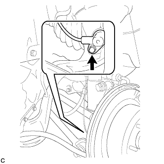
Install the rear speed sensor to the rear axle carrier sub-assembly with the bolt .
- Torque:
- 8.0 N*m { 82 kgf*cm, 71 in.*lbf }
Note
-
Keep the rear speed sensor tip and sensor installation hole free from foreign matter.
-
To prevent interference with the bearing rotor, do not rotate the rear speed sensor body when inserting the rear speed sensor body or after inserting the rear speed sensor body.
-
Do not twist the rear speed sensor wire when installing.
-
-
INSTALL REAR SPEED SENSOR RH (for 4WD)
Tech Tips
Perform the same procedure as the LH side.
-
STABILIZE SUSPENSION (for 4WD)
-
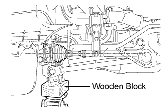
Jack up the rear axle carrier sub-assembly, placing a wooden block underneath to avoid damage. Apply load to the suspension so that the rear drive shaft assembly is positioned horizontally.
CAUTION:
Do not jack up the rear axle carrier sub-assembly too high as the vehicle may fall.
Note
Do not bend the brake dust cover.
Tech Tips
-
If the rear drive shaft assembly cannot be positioned horizontally as shown in the illustration even when the rear axle carrier sub-assembly is jacked up, apply additional load to the vehicle such as by having a person sit in the rear seat.
-
Use the same procedure for the RH side and LH side.
-
-
-
FULLY TIGHTEN REAR NO. 1 SUSPENSION ARM ASSEMBLY LH (for 4WD)
-
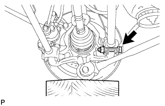
Fully tighten the rear No. 1 suspension arm assembly with the bolt and nut.
- Torque:
- 112 N*m { 1141 kgf*cm, 82 ft.*lbf }
Note
-
Since a stopper nut is used, fully tighten the bolt.
-
The final torque must be applied under standard vehicle height conditions.
-
-
FULLY TIGHTEN REAR NO. 1 SUSPENSION ARM ASSEMBLY RH (for 4WD)
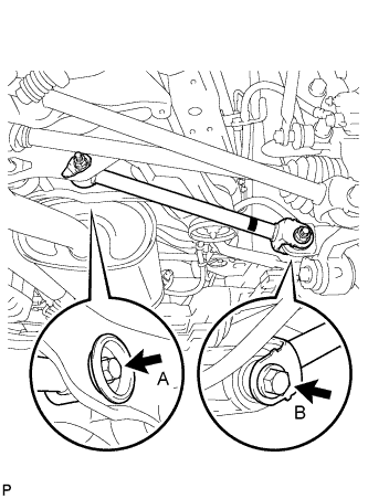
-
Fully tighten the 2 bolts.
- Torque:
- Bolt (A)
- 80 N*m { 815 kgf*cm, 59 ft.*lbf }
- Bolt (B)
- 112 N*m { 1141 kgf*cm, 82 ft.*lbf }
Note
-
Since a stopper nut is used, temporarily tighten the bolt.
-
The final torque must be applied under standard vehicle height conditions.
-
-
FULLY TIGHTEN REAR NO. 2 SUSPENSION ARM ASSEMBLY LH (for 4WD)
-
Align the matchmarks on the adjust cams and rear suspension member sub-assembly.
-
Fully tighten the nut.
- Torque:
- 100 N*m { 1019 kgf*cm, 74 ft.*lbf }
Note
The final torque must be applied under standard vehicle height conditions.
Tech Tips
When fully tightening the nut, keep the rear suspension toe adjust cam sub-assembly from rotating.
-
Fully tighten the bolt.
- Torque:
- 112 N*m { 1141 kgf*cm, 82 ft.*lbf }
Note
-
Since a stopper nut is used, fully tighten the bolt.
-
The final torque must be applied under standard vehicle height conditions.
-
-
FULLY TIGHTEN REAR NO. 2 SUSPENSION ARM ASSEMBLY RH (for 4WD)
Tech Tips
Perform the same procedure as the LH side.
-
FULLY TIGHTEN REAR STRUT ROD ASSEMBLY LH (for 4WD)
-
Fully tighten the bolt.
- Torque:
- 80 N*m { 815 kgf*cm, 59 ft.*lbf }
Note
-
Since a stopper nut is used, fully tighten the bolt.
-
The final torque must be applied under standard vehicle height conditions.
-
Fully tighten the bolt.
- Torque:
- 80 N*m { 815 kgf*cm, 59 ft.*lbf }
Note
-
Since a stopper nut is used, fully tighten the bolt.
-
The final torque must be applied under standard vehicle height conditions.
-
-
FULLY TIGHTEN REAR STRUT ROD ASSEMBLY RH (for 4WD)
Tech Tips
Perform the same procedure as the LH side.
-
INSTALL NO. 3 PARKING BRAKE CABLE ASSEMBLY (for 4WD)
-
Install the No. 3 parking brake cable assembly with the bolt and the nut.
- Torque:
- Bolt
- 39 N*m { 397 kgf*cm, 29 ft.*lbf }
- Nut
- 6.0 N*m { 61 kgf*cm, 53 in.*lbf }
Note
Do not twist the No. 3 parking brake cable assembly when installing it.
-
-
INSTALL NO. 2 PARKING BRAKE CABLE ASSEMBLY (for 4WD)
Tech Tips
Perform the same procedure as the No. 3 parking brake cable assembly.
-
SEPARATE REAR DISC BRAKE CALIPER ASSEMBLY LH (for 4WD)
-
Remove the 2 bolts and separate the rear disc brake caliper assembly.
Note
Use wire or an equivalent tool to keep the brake caliper from hanging down by the flexible hose.
-
-
SEPARATE REAR DISC BRAKE CALIPER ASSEMBLY RH (for 4WD)
Tech Tips
Perform the same procedure as the LH side.
-
REMOVE REAR DISC (for 4WD LH Side)
-
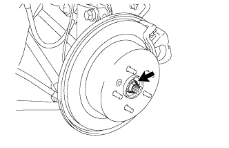
Put matchmarks on the rear disc and the axle hub.
-
Release the parking brake and remove the rear disc.
Tech Tips
If the disc cannot be removed easily, turn and press firmly the shoe adjuster until the wheel comes free.
-
-
REMOVE REAR DISC (for 4WD RH Side)
-
INSPECT REAR AXLE HUB BEARING LOOSENESS (for 4WD LH Side)
-
Using a dial indicator, check for looseness near the center of the rear axle hub and bearing assembly.
Maximum looseness 0 mm (0 in.) Note
Ensure that the dial indicator is set perpendicular to the measurement surface.
Tech Tips
If the looseness exceeds the maximum, replace the rear axle hub and bearing assembly.
-
-
INSPECT REAR AXLE HUB BEARING LOOSENESS (for 4WD RH Side)
Tech Tips
Perform the same procedure as the LH side.
-
INSPECT REAR AXLE HUB RUNOUT (for 4WD LH Side)
-
Using a dial indicator, check for runout on the surface of the rear axle hub and bearing assembly outside the rear axle hub bolt.
Maximum runout 0.08 mm (0.0031 in.) Note
Ensure that the dial indicator is set perpendicular to the measurement surface.
Tech Tips
If the runout exceeds the maximum, replace the rear axle hub and bearing assembly.
-
-
INSPECT REAR AXLE HUB RUNOUT (for 4WD RH Side)
Tech Tips
Perform the same procedure as the LH side.
-
INSTALL REAR DISC (for 4WD LH Side)
-
Align matchmarks and install the rear disc.
Note
When replacing the rear disc with a new one, select the installation position where the rear disc has minimal runout.
-
-
INSTALL REAR DISC (for 4WD RH Side)
Tech Tips
Perform the same procedure as the LH side.
-
INSTALL REAR DISC BRAKE CALIPER ASSEMBLY LH (for 4WD)
-
Install the rear disc brake caliper assembly with the 2 bolts.
- Torque:
- 78 N*m { 795 kgf*cm, 57 ft.*lbf }
-
-
INSTALL REAR DISC BRAKE CALIPER ASSEMBLY RH (for 4WD)
Tech Tips
Perform the same procedure as the LH side.
-
INSTALL REAR AXLE SHAFT NUT LH (for 4WD)
-
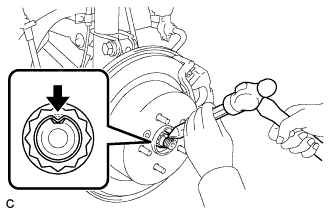
Using a chisel and a hammer, stake the rear axle shaft nut.
-
-
INSTALL REAR AXLE SHAFT NUT RH (for 4WD)
Tech Tips
Perform the same procedure as the LH side.
-
INSTALL REAR WHEELS (for 4WD)
- Torque:
- 103 N*m { 1050 kgf*cm, 76 ft.*lbf }
-
INSTALL NO. 4 EXHAUST PIPE SUPPORT BRACKET
-
Install the No. 4 exhaust pipe support bracket with the 2 bolts.
- Torque:
- 22 N*m { 224 kgf*cm, 16 ft.*lbf }
-
-
INSTALL CENTER EXHAUST PIPE ASSEMBLY
-
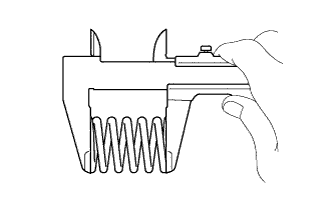
Using vernier calipers, measure the free length of the compression spring.
Minimum 41.5 mm (1.63 in.) Tech Tips
If the length is less than the minimum, replace the compression spring.
-
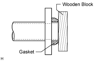
Using a plastic-faced hammer and wooden block, tap in a new gasket until its surface is flush with the front No. 3 exhaust pipe sub-assembly.
Note
-
Tap in the gasket in the correct direction.
-
Do not reuse the removed gasket.
-
Do not push in the gasket while installing the center exhaust pipe assembly.
-
-
Connect the 3 exhaust pipe supports, and install the center exhaust pipe assembly.
-
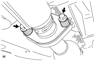
Install the 2 compression springs and 2 bolts.
- Torque:
- 48 N*m { 489 kgf*cm, 35 ft.*lbf }
-
-
INSTALL TAIL EXHAUST PIPE ASSEMBLY
-
Using vernier calipers, measure the free length of the compression spring.
Minimum 40.5 mm (1.59 in.) Tech Tips
If the length is less than the minimum, replace the compression spring.
-
Using a plastic-faced hammer and wooden block, tap in a new gasket until its surface is flush with the center exhaust pipe assembly.
Note
-
Tap in the gasket in the correct direction.
-
Do not reuse the removed gasket.
-
Do not push in the gasket while installing the tail exhaust pipe assembly.
-
-
Connect the exhaust pipe support, and install the tail exhaust pipe assembly.
-
Install the 2 compression springs and 2 bolts.
- Torque:
- 48 N*m { 489 kgf*cm, 35 ft.*lbf }
-
-
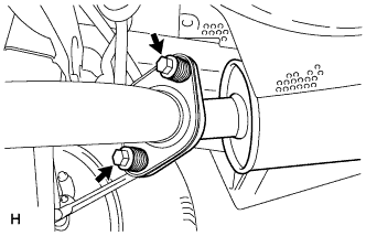
TEMPORARILY TIGHTEN PROPELLER WITH CENTER BEARING SHAFT ASSEMBLY (for 4WD)
-
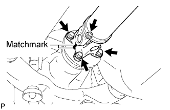
Align the matchmarks on the propeller shaft flange and differential companion flange, and connect the shaft with the 4 bolts, 4 washers and 4 nuts.
-
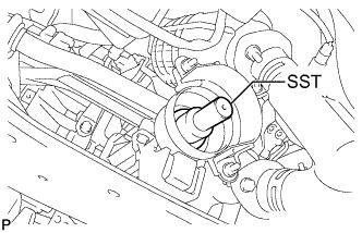
Remove SST from the transaxle.
-
Insert the yoke into the transaxle.
-
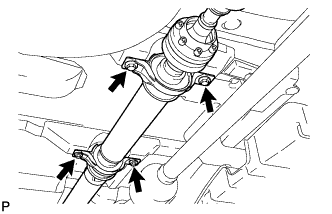
Install the 4 adjusting shims and propeller shaft with center bearing, and temporarily tighten the 4 bolts.
-
Tighten the 4 bolts.
- Torque:
- 74 N*m { 750 kgf*cm, 54 ft.*lbf }
-
-
FULLY TIGHTEN PROPELLER WITH CENTER BEARING SHAFT ASSEMBLY (for 4WD)
-
Remove the piece of cloth from the joint.
-
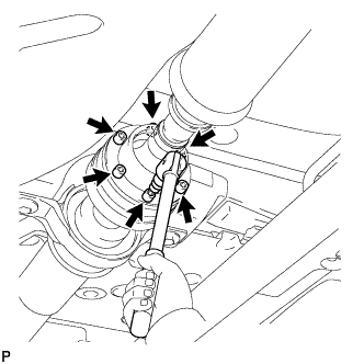
Using a hexagon wrench (6 mm), tighten the 6 bolts.
- Torque:
- 26 N*m { 265 kgf*cm, 19 ft.*lbf }
-
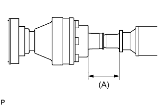
With the vehicle unloaded, adjust the dimension between the rear side of the cover and shaft as shown in the illustration.
(A) 58.0 +/- 0.5 mm (2.283 +/- 0.02 in.) -
Under the same condition as above, adjust the front and rear dimensions between the edge surface of the center support bearing and the edge surface of the cushion respectively as shown, and then tighten the bolts.
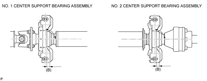
- Torque:
- 37 N*m { 375 kgf*cm, 27 ft.*lbf }
(B) 12.5 +/- 1.0 mm (0.492 +/- 0.039 in.) -
Check that the center line of the bracket is at the right angle in the shaft axial direction.
-
If any vibration or noise occurs, perform joint angle check as follows and replace the adjusting shim with a proper one.
-
Turn the propeller shaft several times by hand to stabilize the center support bearings.
-
Using a jack, raise and lower the differential to stabilize the differential mounting cushion.
-
Remove the transfer dynamic damper.
-
Using SST, measure the transfer installation angle (A) and front propeller shaft installation angle (B).
- SST
- 09370-50010
No. 1 joint angle (A) - (B) = -1.3° to -3.3° -
Using SST, measure the rear propeller shaft installation angle (C) and rear differential shaft installation angle (D).
- SST
- 09370-50010
No. 2 joint angle (C) - (D) = 1.8° to 3.5° 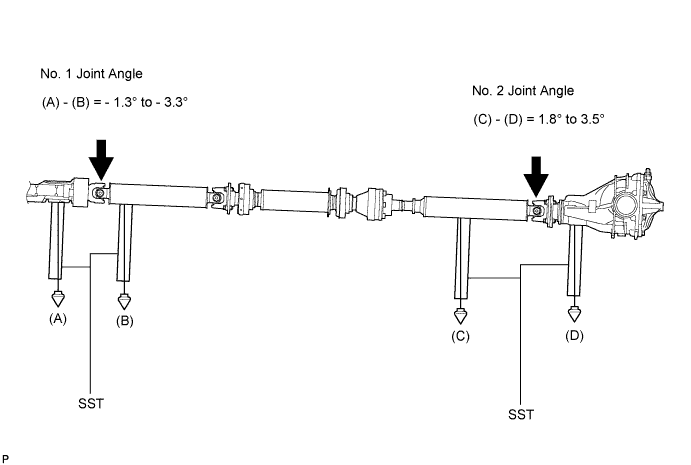
Tech Tips
If the measured angle is not within the specification, adjust it with the center support bearing adjusting shim.
Center support bearing adjusting shim thickness Thickness mm (in.) Thickness mm (in.) 3.2 (0.126) 11.0 (0.433) 4.5 (0.177) 13.5 (0.531) 6.5 (0.256) 15.5 (0.610) 9.0 (0.354) 17.5 (0.689) -
Install the transfer dynamic damper.
- Torque:
- 26 N*m { 265 kgf*cm, 19 ft.*lbf }
-
-
-
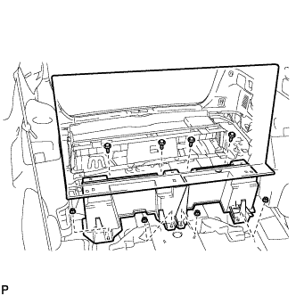
INSTALL FRONT CENTER FLOOR COVER
-
Engage the 4 clips to install the center front floor cover.
-
Install the 4 bolts, 2 screws, and the nut.
-
-
INSTALL FUEL SUCTION TUBE ASSEMBLY WITH PUMP AND GAUGE
-
Install a new gasket to the fuel tank.
-
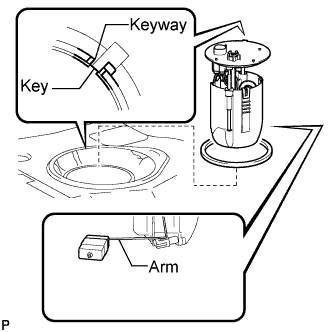
Attach the fuel suction tube with pump and gauge to the fuel tank.
Note
Be careful not to bend the arm of the fuel sender gauge.
-
Align the keyway of the fuel suction tube support with the key of the fuel suction tube with pump and gauge.
-

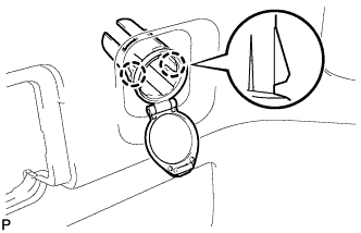
Align the triangle mark on a new fuel pump gauge retainer with the "S" mark on the fuel tank while pushing down the fuel suction tube with pump and gauge, and attach the fuel pump gauge retainer.
-
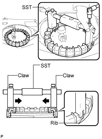
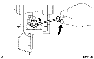
Using a 6 mm socket hexagon wrench, install SST to the fuel pump gauge retainer.
- SST
- 09808-14020 ( 09808-01410, 09808-01420, 09808-01430 )
Tech Tips
-
Engage the SST claws securely with the fuel pump gauge retainer ribs to secure SST.
-
Install SST while pressing the SST claws toward the fuel pump gauge retainer (toward the center of SST).
-
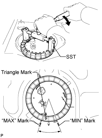
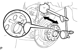
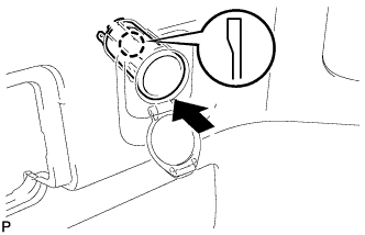
Rotate the fuel pump gauge retainer by hand, then tighten it one complete turn and another half turn using SST. The triangle mark on the fuel pump gauge retainer must be positioned between the "MIN" and "MAX" marks on the fuel tank.
- SST
- 09808-14020 ( 09808-01410, 09808-01420, 09808-01430 )
Note
-
Do not use any tools other than specified in this operation. Damage to the fuel pump gauge retainer or the fuel tank may result.
-
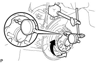
Fully tighten the retainer by turning it clockwise while holding SST down. Do not allow the claw of the tank suction tube support to slip out of its groove on the fuel tank.
Tech Tips
The ribs on the fuel pump gauge retainer can be fitted into the tips of SST.
-
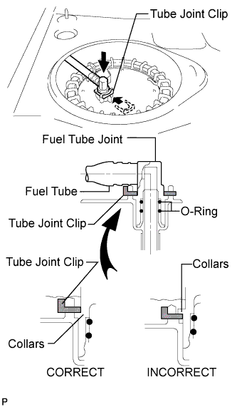
Install the fuel pump tube and the tube joint clip.
Note
-
Check that there are no scratches or foreign objects on the connecting part.
-
Check that the fuel tube joint is inserted securely.
-
Check that the tube joint clip is correctly located on the collar of the fuel tube joint.
-
After installing the tube joint clip, check that the fuel tube joint has not been pulled out of position.
-
-
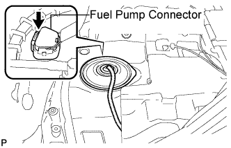
Connect the fuel pump connector.
-
-
CONNECT CABLE TO NEGATIVE BATTERY TERMINAL
-
INSPECT FOR FUEL LEAK
-
Check fuel pump operation.
-
Connect the intelligent tester to the DLC3.
-
Turn the ignition switch on (IG) and turn the intelligent tester main switch on.
Note
Do not start the engine.
-
Select the following menu items: DIAGNOSIS / ENHANCED OBD II / ACTIVE TEST / FUEL PUMP / SPD.
-
Check for pressure in the fuel inlet tube from the fuel line. Check that sounds of fuel flowing from the fuel tank can be heard. If no sounds can be heard, check the integration relay, fuel pump, ECM and wiring connectors.
-
-
Check for fuel leaks.
-
Check that there are no fuel leaks from the fuel system after doing any maintenance or repairs. If there is a fuel leak, repair or replace parts as necessary.
-
-
Turn the ignition switch off.
-
Disconnect the intelligent tester from the DLC3.
-
-
DISCONNECT CABLE FROM NEGATIVE BATTERY TERMINAL
Note
When disconnecting the cable, some systems need to be initialized after the cable is reconnected Click here.
-
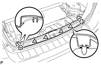
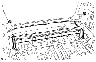
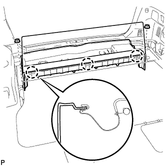
INSTALL REAR FLOOR SERVICE HOLE COVER
-
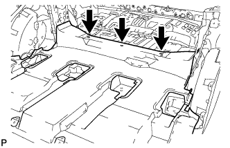
Install new butyl tape to the rear floor service hole cover.
-
Install the rear floor service hole cover.
-
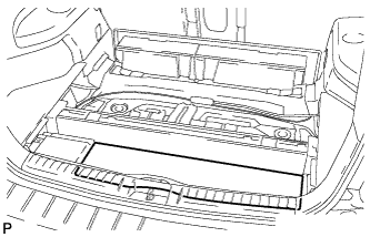
Install the front floor carpet.
-
Install the front floor carpet with the 3 clips. (w/ rear No. 2 seat)
-
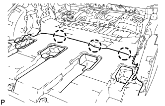
Engage the 3 claws to install the front floor carpet. (w/o rear No. 2 seat)
-
-
-
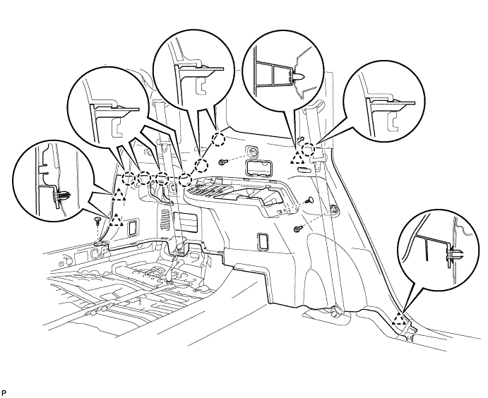
INSTALL DECK TRIM SIDE PANEL ASSEMBLY LH
-
Engage the 4 clips and the 7 claws.
-
Install the 2 clips.
-
Install the deck trim side panel assembly LH with the 2 bolts.
-
-
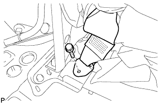
INSTALL REAR NO. 1 SEAT OUTER BELT ASSEMBLY LH
-
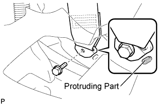
Connect the floor anchor end of the rear No. 1 seat outer belt assembly and install the bolt.
- Torque:
- 42 N*m { 428 kgf*cm, 31 ft.*lbf }
Note
Do not allow the anchor part of the rear No. 1 seat outer belt assembly to overlap the protruding part of the floor panel.
-
-
INSTALL FRONT DECK SIDE TRIM COVER LH
-
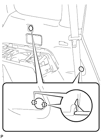
Engage the 4 claws and install the 2 front deck side trim covers LH.
-
-
INSTALL NO. 2 DECK SIDE TRIM HOOK
-
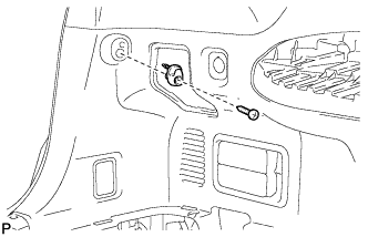
Install the No. 2 deck side trim hook with the screw.
-
-
INSTALL ROPE HOOK ASSEMBLY (for LH Side)
-
for Front Side:
-
Install the rope hook assembly with the bolt.
- Torque:
- 6.5 N*m { 66 kgf*cm, 58 in.*lbf }
-
Engage the 2 claws.
-
-
for Rear Side:
-
Install the rope hook assembly with the bolt.
- Torque:
- 6.5 N*m { 66 kgf*cm, 58 in.*lbf }
-
Engage the 2 claws.
-
-
-
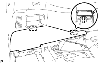
INSTALL REAR DECK TRIM COVER (w/o Remote Folding Function)
-
Engage the 10 claws and install the rear deck trim cover.
-
-
INSTALL RECLINING REMOTE CONTROL LEVER BEZEL LH (w/ Remote Folding Function)
-
Engage the 5 claws and install the reclining remote control bezel LH.
-
-
INSTALL REAR POWER OUTLET SOCKET COVER
-
Engage the 2 claws and install the rear power outlet socket cover.
-
-
INSTALL REAR POWER POINT SOCKET ASSEMBLY
-
Engage the claw and install the rear power point socket assembly.
-
Connect the connector.
-
-
INSTALL REAR COMBINATION LIGHT SERVICE COVER LH
-
Engage the 2 guides and 6 claws, and install the rear combination light service cover LH.
-
-
INSTALL SIDE TRIM COVER LH
-
Engage the 10 claws and install the side trim cover LH.
-
-
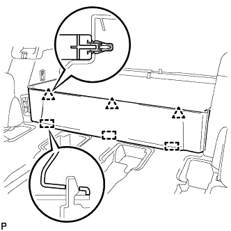
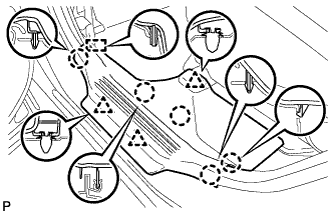
INSTALL DECK SIDE TRIM LH
-
Engage the 3 guides and 4 claws as shown in the illustration.
-
Install the deck side trim LH with the bolt.
-
-
INSTALL DECK SIDE TRIM COVER NO.2
-
Engage the 2 claws and install the deck side trim cover LH.
-
-
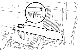
INSTALL REAR FLOOR FINISH PLATE
-
Engage the 4 clips and the 4 claws, and install the rear floor finish plate.
-
-
INSTALL REAR NO. 2 SEAT ASSEMBLY (w/ Rear No. 2 Seat)
-
Install the rear No. 2 seat assembly with the 4 bolts.
- Torque:
- 37 N*m { 377 kgf*cm, 27 ft.*lbf }
-
-
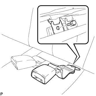
CONNECT REAR SEAT LAP TYPE BELT ASSEMBLY LH (w/ Rear No. 2 Seat)
-
Install the rear seat lap type belt assembly LH with the bolt.
- Torque:
- 42 N*m { 428 kgf*cm, 31 ft.*lbf }
Note
After installing the belt, check that it is not twisted.
-
-
CONNECT REAR SEAT LAP TYPE BELT ASSEMBLY RH (w/ Rear No. 2 Seat)
-
Install the rear seat lap type belt assembly RH with the bolt.
- Torque:
- 42 N*m { 428 kgf*cm, 31 ft.*lbf }
Note
After installing the belt, check that it is not twisted.
-
-
INSTALL REAR NO. 2 SEAT INNER BELT ASSEMBLY (w/ Rear No. 2 Seat)
-
Install the rear No. 2 seat inner belt assembly with the bolt.
- Torque:
- 42 N*m { 428 kgf*cm, 31 ft.*lbf }
Note
Do not allow the anchor part of the rear No. 2 seat inner belt assembly to overlap the protruding part of the rear No. 2 seat bracket.
Tech Tips
Use the same procedure for the RH side and LH side.
-
-
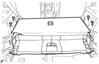
INSTALL REAR DECK FLOOR BOX (w/o Rear No. 2 Seat)
-
Install the rear deck floor box with the 2 nuts.
-
-
INSTALL DECK FLOOR BOARD ASSEMBLY (w/o Rear No. 2 Seat)
-
Install the 2 nuts and the deck floor board assembly.
-
Engage the 3 claws.
-
-
INSTALL REAR MAT
-
Install the rear mat.
-
-
INSTALL DECK FLOOR BOARD ASSEMBLY (w/ Rear No. 2 Seat)
-
Install the rear deck floor board assembly with the 4 nuts and 4 bolts.
-
-
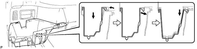
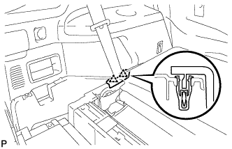
INSTALL DECK SIDE TRIM BOX LH
-
Install the deck side trim box LH as shown in the illustration.
-
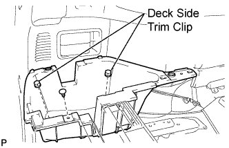
Install the 2 deck side trim clips and the clip.
-
-
INSTALL REAR SEAT SIDE COVER LH (w/ Rear No. 2 Seat)
-
Engage the 2 clips and install the rear seat side cover LH.
-
-
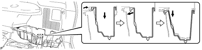
INSTALL DECK SIDE TRIM BOX RH
-
Install the deck side trim box RH as shown in the illustration.
-
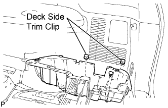
Install the 2 deck side trim clips and the clip.
-
-
INSTALL JACK CARRIER ASSEMBLY (for LHD)
-

Engage the 3 claws, and install the jack carrier assembly.
-
-
INSTALL JACK CARRIER ASSEMBLY (for RHD)
-
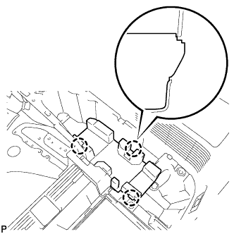
Engage the 3 claws, and install the jack carrier assembly.
-
-
INSTALL JACK ASSEMBLY (for LHD)
-
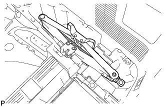
Install the jack assembly.
-
-
INSTALL JACK ASSEMBLY (for RHD)
-
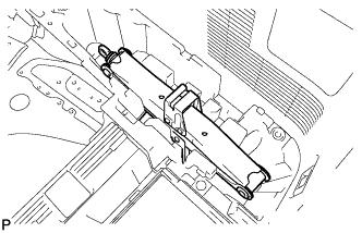
Install the jack assembly.
-
-
INSTALL JACK CARRIER CUSHION (for LHD)
-
Install the jack carrier cushion.
-
-
INSTALL JACK CARRIER CUSHION (for RHD)
-

Install the jack carrier cushion.
-
-
INSTALL JACK CARRIER SUPPORT
-
INSTALL REAR SEAT SIDE COVER RH (w/ Rear No. 2 Seat)
-
Engage the 2 clips and install the rear seat side cover RH.
-
-
INSTALL REAR NO. 1 FLOOR BOARD (w/o Rear No. 2 Seat)
-
Engage the 3 guides and 3 clips and install the rear No. 1 floor board.
-
-
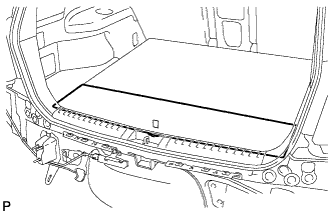
INSTALL TONNEAU COVER ASSEMBLY (w/ Tonneau Cover)
-
INSTALL NO. 2 DECK BOARD SUB-ASSEMBLY
-
Engage the 2 guides and install the No. 2 deck board sub-assembly.
-
-
INSTALL NO. 3 DECK BOARD SUB-ASSEMBLY
-
Engage the 2 guides and install the No. 3 deck board sub-assembly.
-
-
INSTALL DECK BOARD ASSEMBLY
-
Install the deck board sub-assembly.
-
-
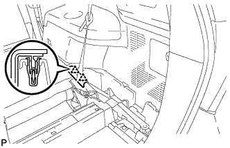
INSTALL REAR DOOR OPENING TRIM WEATHERSTRIP LH
-
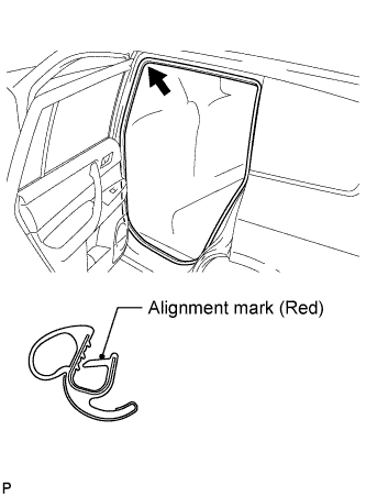
Align the alignment mark (red) on the weatherstrip with the protruding portion on the body indicated by the arrow in the illustration, and install the rear door opening trim weatherstrip LH.
Note
After installation, check that the corners fit correctly.
-
-
INSTALL REAR DOOR SCUFF PLATE LH
-
Engage the guide, 3 clips and 5 claws, and install the rear door scuff plate LH.
-
-
INSTALL REAR NO. 1 SEAT ASSEMBLY RH
-
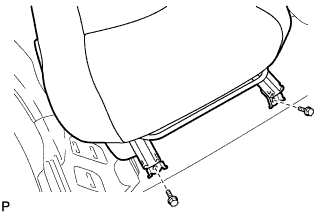
Temporarily install the 2 bolts on the front side of the seat.
-
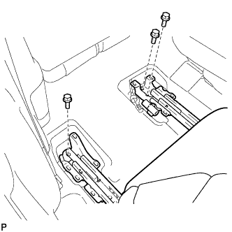
Temporarily Install the 3 bolts on the rear side of the seat.
-
Install the rear No. 1 seat assembly with the 5 bolts.
- Torque:
- 37 N*m { 377 kgf*cm, 27 ft.*lbf }
-
-
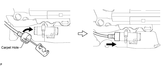
INSTALL REAR NO. 1 SEAT LOCK CABLE ASSEMBLY RH (w/ Remote Folding Function)
-
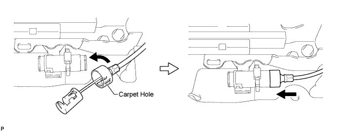
Remove the rear seat reclining control cable from the carpet hole.
-
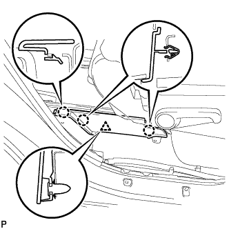
Connect the rear seat reclining control cable as shown in the illustration.
-
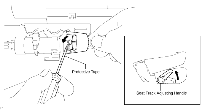
Connect the rear No. 1 seat lock cable assembly as shown in the illustration.
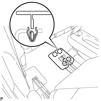
-
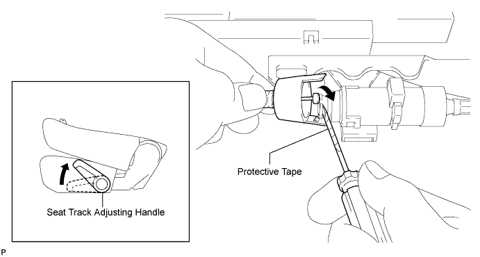
Engage the 2 claws and connect the rear No. 1 seat lock cable assembly as shown in the illustration.
-
Return the seatback to the upright position.
-
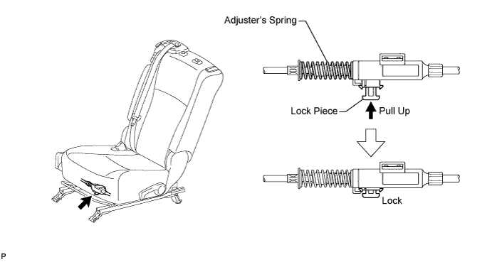
Pull up the adjuster's lock piece to lock it as shown in the illustration.
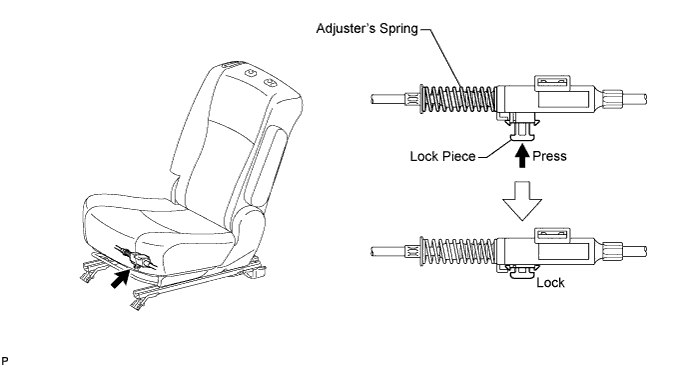
Note
When pressing the lock piece, make sure the adjuster's spring is not compress.
-
-
INSPECT REAR SEAT SLIDE ADJUSTER LOCK (for RH Side)
-
Check that the left and right adjusters lock simultaneously when sliding the seat.
-
If the left and right adjusters do not lock simultaneously, adjust by loosening the bolts securing the seat.
-
-
INSTALL REAR SEAT LEG SIDE COVER RH
-
Engage the clip.
-
Engage the 3 claws and install the rear seat leg side cover.
-
-
INSTALL REAR INNER TRACK BRACKET COVER RH
-
Engage the 4 claws and install the rear inner track bracket cover.
-
-
INSTALL REAR OUTER TRACK BRACKET COVER RH
-
Engage the 4 claws and install the rear outer track bracket cover.
-
-
INSTALL SEAT TRACK BRACKET COVER RH
-
Engage the 8 claws and install the 2 seat track bracket covers.
-
-
INSTALL REAR SEAT HEADREST ASSEMBLY (for RHD)
-
INSTALL REAR NO. 1 SEAT ASSEMBLY LH
-
Temporarily install the 2 bolts on the front side of the seat.
-
Temporarily install the 3 bolts on the rear side of the seat.
-
Install the rear No. 1 seat assembly with the 5 bolts.
- Torque:
- 37 N*m { 377 kgf*cm, 27 ft.*lbf }
-
-
CONNECT REAR NO. 1 SEAT LOCK CABLE ASSEMBLY LH (w/ Remote Folding Function)
-
Remove the rear seat reclining control cable from the carpet hole.
-
Connect the rear seat reclining control cable as shown in the illustration.
-
Connect the rear No. 1 seat lock cable assembly as shown in the illustration.
-
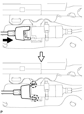
Engage the 2 claws and connect the rear No. 1 seat lock cable assembly as shown in the illustration.
-
Return the seatback to the upright position.
-
Pull up the adjuster's lock piece to lock it as shown in the illustration.
Note
When pressing the lock piece, make sure the adjuster's spring is not compress.
-
-
INSPECT REAR SEAT SLIDE ADJUSTER LOCK (for LH Side)
-
Check that the left and right adjusters lock simultaneously when sliding the seat.
-
If the left and right adjusters do not lock simultaneously, adjust by loosening the bolts securing the seat.
-
-
INSTALL REAR SEAT LEG SIDE COVER LH
-
Engage the clip.
-
Engage the 3 claws and install the rear seat leg side cover.
-
-
INSTALL REAR INNER TRACK BRACKET COVER LH
-
Engage the 4 claws and install the rear inner track bracket cover.
-
-
INSTALL REAR OUTER TRACK BRACKET COVER LH
-
Engage the 4 claws and install the rear outer track bracket cover.
-
-
INSTALL SEAT TRACK BRACKET COVER LH
-
Engage the 8 claws and install the 2 rear seat track bracket covers.
-
-
INSTALL REAR SEAT HEADREST ASSEMBLY (for LH Side)
-
INSTALL REAR CENTER SEAT ASSEMBLY
-
CONNECT CABLE TO NEGATIVE BATTERY TERMINAL
Note
When disconnecting the cable, some systems need to be initialized after the cable is reconnected Click here.
-
INSPECT SRS WARNING LIGHT
-
Inspect the SRS warning light Click here.
-
-
INSPECT EXHAUST GAS LEAK
If exhaust gas is leaking, repair the leak. Replace damaged or worn parts as necessary.
-
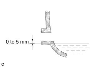
INSPECT AND ADJUST TRANSFER OIL (for 4WD)
-
Remove the No. 1 transfer case plug and gasket.
-
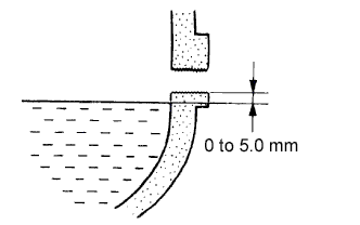
Check the oil level is within 0 to 5 mm (0 to 0.20 in.) below the lowest end of the hole for the No. 1 transfer case plug.
Note
-
When changing oil, recheck the oil level after driving.
-
Excessively large or small quantity of oil may cause some trouble.
-
-
When the oil level is too low, check for oil leakage.
-
Tighten the No. 1 transfer case plug with a new gasket.
- Torque:
- 49 N*m { 500 kgf*cm, 36 ft.*lbf }
-
-
INSPECT REAR WHEEL ALIGNMENT (for 4WD)
Tech Tips
-
CHECK ABS SPEED SENSOR SIGNAL (for 4WD)
Tech Tips