AIR CONDITIONING SYSTEM (for Automatic Air Conditioning System), Diagnostic DTC:B1451/51
| DTC Code | DTC Name |
|---|---|
| B1451/51 | Compressor Solenoid Circuit |
DESCRIPTION
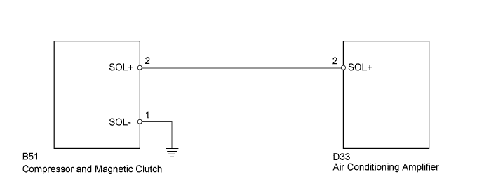
In this circuit, the compressor receives a refrigerant compression demand signal from the air conditioning amplifier.
Based on this signal, the compressor changes the degree of refrigerant compression.
| DTC No. | DTC Detection Condition | Trouble Area |
|---|---|---|
| B1451/51 | Open or short in solenoid of externally changeable compressor circuit |
|
WIRING DIAGRAM
INSPECTION PROCEDURE
PROCEDURE
-
READ VALUE USING INTELLIGENT TESTER (REG CTRL CURRNT)
-
Connect the intelligent tester to the DLC3.
-
Turn the ignition switch on (IG) and turn the intelligent tester main switch on.
-
Select the items below in the Data List, and read the value displayed on the intelligent tester.
Data List / Air Conditioner: Tester Display Measurement Item/Range Normal Condition Diagnostic Note Reg Ctrl Currnt Regulator control current /
Min.: 0 A
Max.: 0.997 A
Value changes between 0 A and 0.997 A in accordance with compressor operation - OK The display is as specified in the normal condition column. Result Result Proceed to NG A OK (Checking from PROBLEM SYMPTOMS TABLE) B OK (Checking from DTC) C
B 
PROCEED TO NEXT CIRCUIT INSPECTION SHOWN IN PROBLEM SYMPTOMS TABLE Click here
C
REPLACE AIR CONDITIONING AMPLIFIER Click here
A 
-
-
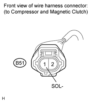
INSPECT COMPRESSOR AND MAGNETIC CLUTCH
-
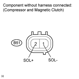
Disconnect the B51 compressor and magnetic clutch connector.
-
Measure the resistance according to the value(s) in the table below.
Standard resistance Tester Connection Condition Specified Condition B51-1 (SOL-) - B51-2 (SOL+) 25°C (77°F) 10.1 to 11.1 Ω
NG
REPLACE COMPRESSOR AND MAGNETIC CLUTCH Click here
OK
-
-
CHECK HARNESS AND CONNECTOR (COMPRESSOR AND MAGNETIC CLUTCH - AIR CONDITIONING AMPLIFIER)
-
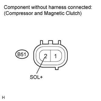
Disconnect the B51 compressor and magnetic clutch connector.
-
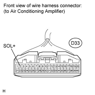
Disconnect the D33 amplifier connector.
-
Measure the resistance according to the value(s) in the table below.
Standard resistance Tester Connection Condition Specified Condition B51-2 (SOL+) - D33-2 (SOL+) Always Below 1 Ω B51-2 (SOL+) - Body Ground Always 10 kΩ or higher
NG
REPAIR OR REPLACE HARNESS OR CONNECTOR
OK
-
-
CHECK HARNESS AND CONNECTOR (COMPRESSOR AND MAGNETIC CLUTCH - BODY GROUND)
-
Disconnect the B51 compressor and magnetic clutch connector.
-
Measure the resistance according to the value(s) in the table below.
Standard resistance Tester Connection Condition Specified Condition B51-1 (SOL-) - Body Ground Always Below 1 Ω
NG
REPAIR OR REPLACE HARNESS OR CONNECTOR
OK 
REPLACE AIR CONDITIONING AMPLIFIER Click here
-