If the sensor rotor needs to be replaced, replace it together with the rear axle hub and bearing assembly with rear speed sensor.
- Click here
INSTALL REAR SPEED SENSOR
-
Clean the contact surface between the rear axle hub and bearing assembly and a new rear speed sensor.
Note:Prevent foreign matter from attaching to the sensor rotor.
-
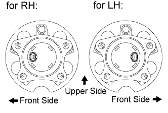
Place the rear speed sensor on the axle hub so that the connector is positioned as shown in the illustration.
-
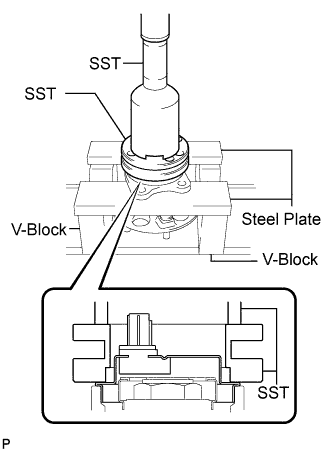
Using SST, a steel plates, V-blocks and press, install a new rear speed sensor to the rear axle hub and bearing assembly.
09214-76011 09213-58013 Note:
-
Keep the rear speed sensor away from magnets.
-
Do not use a hammer to install the rear speed sensor.
-
Check that there is no foreign matter such as iron chips on the detecting portion of the rear speed sensor.
-
Slowly press in the rear speed sensor straight.
-
-
- Click here
INSTALL REAR AXLE HUB AND BEARING ASSEMBLY WITH REAR SPEED SENSOR
-
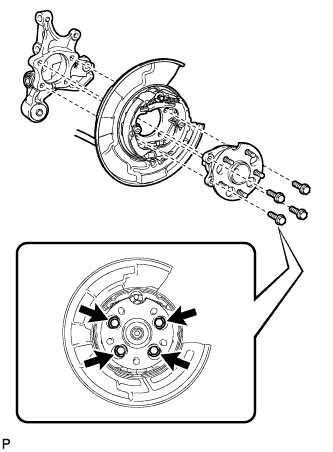
Install the parking brake assembly and the rear axle hub and bearing assembly with the 4 bolts.
75 N*m 764 kgf*cm 55 ft.*lbf Note:Do not twist the No. 3 parking brake cable assembly when installing it.
-
- Click here
INSPECT REAR AXLE HUB BEARING LOOSENESS
-
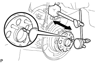
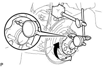
Using a dial indicator, check for looseness near the center of the axle hub.
Maximum looseness 0 mm (0 in.) Note:Ensure that the dial indicator is set perpendicular to the measurement surface.
If the looseness exceeds the maximum, replace the rear axle hub and bearing assembly.
-
- Click here
INSPECT REAR AXLE HUB RUNOUT
-
Using a dial indicator, check for runout on the surface of the axle hub outside the hub bolt.
Maximum runout 0.08 mm (0.0031 in.) Note:Ensure that the dial indicator is set perpendicular to the measurement surface.
If the runout exceeds the maximum, replace the rear axle hub and bearing assembly.
-
- Click here
INSTALL REAR DISC
-
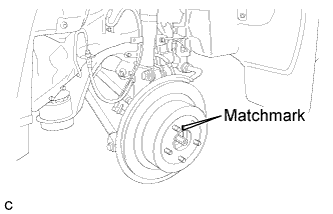
Align matchmarks and install the rear disc.
Note:When replacing the rear disc with a new one, select the installation position where the rear disc has minimal runout.
-
- Click here
INSTALL REAR DISC BRAKE CALIPER ASSEMBLY
-
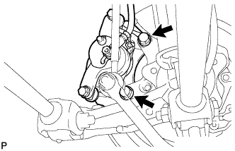
Install the rear disc brake caliper assembly with the 2 bolts.
78 N*m 795 kgf*cm 57 ft.*lbf
-
- Click here
INSTALL REAR SPEED SENSOR WIRE
-
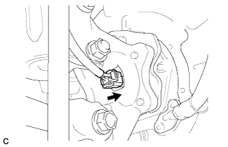
Connect the connector to the rear speed sensor.
-
- Click here
INSTALL REAR WHEEL
103 N*m 1050 kgf*cm 76 ft.*lbf - Click here
CONNECT CABLE TO NEGATIVE BATTERY TERMINAL
Note:When disconnecting the cable, some systems need to be initialized after the cable is reconnected. (Click here)
- Click here
INSPECT AND ADJUST REAR WHEEL ALIGNMENT
Tip:(Click here).
- Click here
CHECK FOR REAR SPEED SENSOR SIGNAL
Tip:(Click here).