VEHICLE STABILITY CONTROL SYSTEM, Diagnostic DTC:C1379
| DTC Code | DTC Name |
|---|---|
| C1379 | Downhill Assist Control Switch Malfunction (Test Mode DTC) |
DESCRIPTION
DTC C1379 will be deleted when the downhill assist control switch sends a downhill assist control operation signal or when Test Mode ends. DTC C1379 is output only in Test Mode.
| DTC Code | DTC Detection Condition | Trouble Area |
|---|---|---|
| C1379 | Detected only during Test Mode. | Downhill assist control switch |
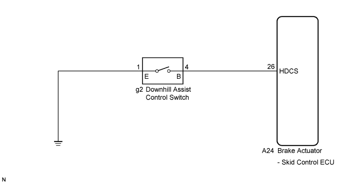
WIRING DIAGRAM
INSPECTION PROCEDURE
Note
When replacing the brake actuator assembly, perform zero point calibration Click here.
PROCEDURE
-
READ VALUE ON INTELLIGENT TESTER (DOWNHILL ASSIST CONTROL SWITCH)
-
Connect the intelligent tester to the DLC3.
-
Turn the ignition switch on (IG).
-
Select the Data List mode on the intelligent tester Click here.
ABS / VSC / TRC: Tester Display Measurement Item/Range Normal Condition Diagnostic Note Downhill Assist Control Switch Downhill assist control switch / ON or OFF ON: Switch ON
OFF: Switch OFF
- -
Using the intelligent tester, check the switch condition on the intelligent tester changes according to downhill assist control switch operation.
OK The intelligent tester displays ON or OFF according to downhill assist control switch operation.
NG 
INSPECT DOWNHILL ASSIST CONTROL SWITCH Click here
OK 
-
-
PERFORM TEST MODE (SIGNAL CHECK)
-
Turn the ignition switch off.
-
Perform the sensor check in the Test Mode procedure Click here.
OK All Test Mode DTCs are erased. Tech Tips
If troubleshooting has been carried out according to the Problem Symptoms Table, refer back to the table and proceed to the next step Click here.
NG 
REPLACE BRAKE ACTUATOR ASSEMBLY Click here
OK 
CHECK FOR INTERMITTENT PROBLEMS (SYMPTOM SIMULATION) Click here
-
-
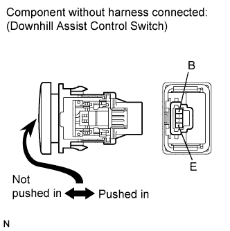
INSPECT DOWNHILL ASSIST CONTROL SWITCH
-
Turn the ignition switch off.
-
Make sure that there is no looseness at the locking part and the connecting part of the connector.
-
Disconnect the downhill assist control switch connector.
-
Measure the resistance according to the value(s) in the table below.
Standard resistance Tester Connection Switch Condition Specified Condition 4 (B) - 1 (E) Switch is pushed in Below 1 Ω 4 (B) - 1 (E) Switch is not pushed in 10 kΩ or higher Note
Check the downhill assist control switch signal after replacement Click here.
NG
REPLACE DOWNHILL ASSIST CONTROL SWITCH Click here
OK
-
-
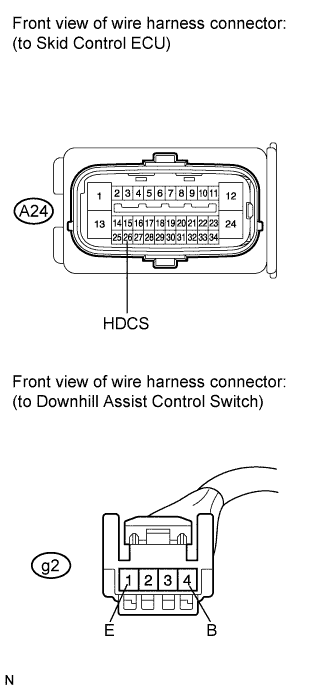
CHECK HARNESS AND CONNECTOR (SKID CONTROL ECU - DOWNHILL ASSIST CONTROL SWITCH)
-
Make sure that there is no looseness at the locking part and the connecting part of the connector.
-
Disconnect the skid control ECU connector.
-
Measure the resistance according to the value(s) in the table below.
Standard resistance Tester Connection Condition Specified Condition A24-26 (HDCS) - g2-4 (B) Always Below 1 Ω A24-26 (HDCS) - Body ground Always 10 kΩ or higher g2-1 (E) - Body ground Always Below 1 Ω Tech Tips
If troubleshooting has been carried out according to the Problem Symptoms Table, refer back to the table and proceed to the next step Click here.
NG
REPAIR OR REPLACE HARNESS OR CONNECTOR
OK
REPLACE BRAKE ACTUATOR ASSEMBLY Click here
-