AIR CONDITIONING SYSTEM (for Manual Air Conditioning System), Diagnostic DTC:B1479/79
| DTC Code | DTC Name |
|---|---|
| B1479/79 | Flow Sensor Circuit |
DESCRIPTION
The A/C flow sensor, which is mounted on the compressor and magnetic clutch, is used to detect the amount of refrigerant flow. The A/C flow sensor converts the amount of refrigerant flow that is detected to a voltage value to send it to the air conditioning amplifier. The voltage value sent from the A/C flow sensor changes depending on the amount of refrigerant flow. As the amount of refrigerant flow becomes larger, the voltage becomes lower. As the amount of refrigerant flow becomes smaller, the voltage becomes higher. The air conditioning amplifier supplies 5 V to the A/C flow sensor and monitors changes in the voltage value sent from the A/C flow sensor. The air conditioning amplifier then sends a signal to the ECM via CAN communication to allow the ECM to control the engine speed while the air conditioning is on.
| DTC No. | DTC Detection Condition | Trouble Area |
|---|---|---|
| B1479/79 | Open or short in A/C flow sensor circuit |
|
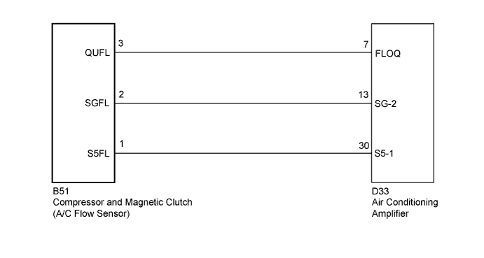
WIRING DIAGRAM
INSPECTION PROCEDURE
PROCEDURE
-
READ VALUE USING INTELLIGENT TESTER
-
Connect the intelligent tester to the DLC3.
-
Turn the ignition switch on (IG).
-
Turn the intelligent tester on.
-
Enter the following menus: Body Electrical / Air Conditioner / Data List.
-
Check the value(s) by referring to the table below.
Air Conditioner Tester Display Measurement Item/Range Normal Condition Diagnostic Note Flow Sensor A/C flow sensor /
Min.: 0 V
Max.: 5 V
Ignition switch on (IG): 0.3 to 4.7 V A/C flow sensor is malfunctioning when a constant value below 0.3 V or higher than 4.7 V is displayed continuously for more than 4 seconds. OK The display is as specified in the Normal Condition column. Result Result Proceed to OK (When troubleshooting according to Problem Symptoms Table) A OK (When troubleshooting according to the DTC) B NG (When a constant value below 0.3 V or higher than 4.7 V is displayed continuously for more than 4 seconds) C
B 
REPLACE AIR CONDITIONING AMPLIFIER Click here
C 
REPLACE COMPRESSOR AND MAGNETIC CLUTCH (A/C FLOW SENSOR) Click here
A 
-
-
READ VALUE USING INTELLIGENT TESTER
-
Connect the intelligent tester to the DLC3.
-
Turn the ignition switch on (IG).
-
Turn the intelligent tester on.
-
Enter the following menus: Body Electrical / Air Conditioner / Data List.
-
Check the value(s) by referring to the table below.
Air Conditioner Tester Display Measurement Item/Range Normal Condition Diagnostic Note A/C Cutoff Signal A/C control cutoff signal /
OFF or ON
A/C switch on: OFF
A/C switch off: ON
- Result Result Proceed to Value in Data List indicates OFF A Value in Data List indicates ON B
B
PROCEED TO NEXT SUSPECTED AREA SHOWN IN PROBLEM SYMPTOMS TABLE Click here
A
-
-
REPLACE COMPRESSOR AND MAGNETIC CLUTCH (A/C FLOW SENSOR)
-
Replace the Compressor and magnetic clutch (A/C flow sensor) Click here.
Tech Tips
Since the Compressor and magnetic clutch (A/C flow sensor) cannot be inspected while it is removed from the vehicle, replace the compressor and magnetic clutch (A/C flow sensor) with a new or a known good one and check that the condition returns to normal.
-
Check for the DTC.
Result Result Proceed to DTC B1479/79 is not output A DTC B1479/79 is output B
B
CHECK HARNESS AND CONNECTOR (COMPRESSOR AND MAGNET (A/C FLOW SENSOR) - A/C AMPLIFIER) Click here
A 
END
-
-
CHECK HARNESS AND CONNECTOR (COMPRESSOR AND MAGNET (A/C FLOW SENSOR) - A/C AMPLIFIER)
-
Disconnect the air conditioning amplifier connector.
-
Measure the resistance according to the value(s) in the table below.
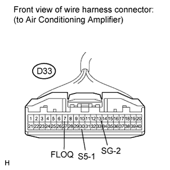
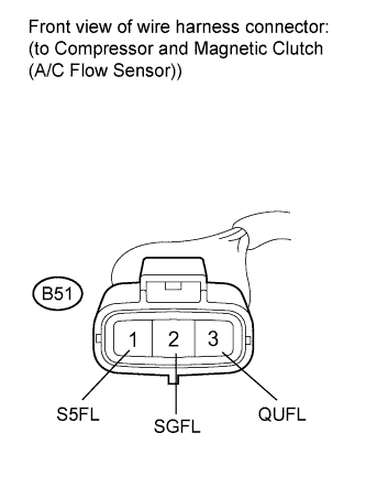
Standard Resistance Tester Connection Condition Specified Condition D33-7 (FLOQ) - B51-3 (QUFL) Always Below 1 Ω D33-13 (SG-2) - B51-2 (SGFL) Always Below 1 Ω D33-30 (S5-1) - B51-1 (S5FL) Always Below 1 Ω D33-7 (FLOQ) - Body ground Always 10 kΩ or higher D33-13 (SG-2) - Body ground Always 10 kΩ or higher D33-30 (S5-1) - Body ground Always 10 kΩ or higher
NG
REPAIR OR REPLACE HARNESS OR CONNECTOR
OK
REPLACE AIR CONDITIONING AMPLIFIER Click here
-