SHIFT AND SELECT TRANSMISSION CONTROL CABLE INSTALLATION

-
CONNECT TRANSMISSION CONTROL CABLE ASSEMBLY
-
Pass the control cable assembly through the floor hole.
-
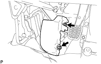
Install the transmission control cable assembly with the 2 bolts.
- Torque:
- 5.5 N*m { 56 kgf*cm, 49 in.*lbf }
-
Wide body LHD steering position type:
-
Install the control cable bracket No.3 to the transmission control cable assembly.
-
Install the control cable bracket No.3 with the 2 nuts.
- Torque:
- 5.5 N*m { 56 kgf*cm, 49 in.*lbf }
-
-
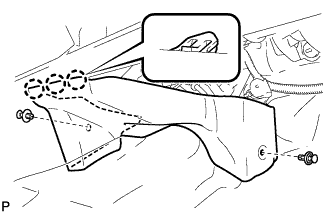
Install the front floor footrest with the 2 nuts.
- Torque:
- 5.0 N*m { 51 kgf*cm, 44 in.*lbf }
-
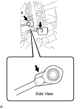
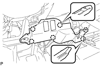
Install the transmission control cable assembly to the shift lever.
Note
Install the transmission control cable assembly so that the end section of the select cable indicated by the arrow, as shown in the side view, (A in the illustration) faces upward.
-
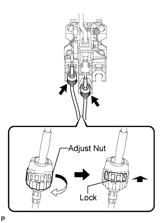
Turn the control cable assembly adjust nut clockwise 180°. While holding the adjust nut, push in the locks.
-
Install the control cable assembly to the shift lever.
Tech Tips
When the cable is installed to the shift lever, the locks are released and the adjust nut rotates 180°. Then, the locks are engaged again.
Note
Make sure that the control cable assembly is firmly installed to the shift lever.
-
-
INSTALL TRANSMISSION CONTROL CABLE ASSEMBLY
-
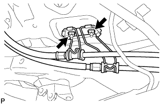
Install the control cable bracket No.2 to the transmission control cable assembly.
-
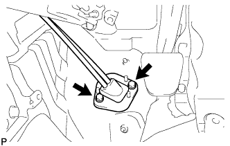
Install the control cable bracket No.2 with the 2 nuts.
- Torque:
- 5.5 N*m { 56 kgf*cm, 49 in.*lbf }
-
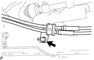
Install the clamp with the bolt.
- Torque:
- 14 N*m { 143 kgf*cm, 10 ft.*lbf }
-
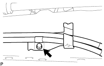
Install the control cable support to the control cable assembly.
-
Install the control cable support with the bolt.
- Torque:
- 14 N*m { 143 kgf*cm, 10 ft.*lbf }
-
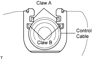
Install new 2 clips to the control cable bracket No.1.
-
Install the transmission control cable assembly to the control cable bracket No.1.
Note
-
Be sure that A claws of the clips are firmly engaged into the bracket grooves.
-
Be sure the cable is set in the clip with both B claws erected to prevent slippage of the cable in the opposite direction.
-
-
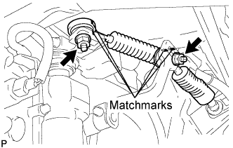
Align the matchmarks on the control cable assembly and the outer lever.
-
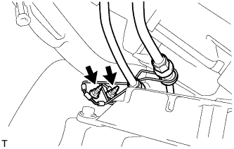
Install the transmission control cable assembly to the outer lever with the 2 nuts.
- Torque:
- 37 N*m { 377 kgf*cm, 27 ft.*lbf }
-
-
INSTALL INSTRUMENT PANEL FINISH PANEL LOWER CENTER
-
Engage the 8 claws and install the instrument panel finish panel lower center.
-
-
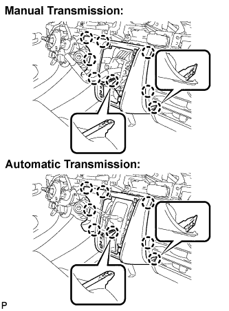
INSTALL SHIFTING HOLE COVER ASSEMBLY
-
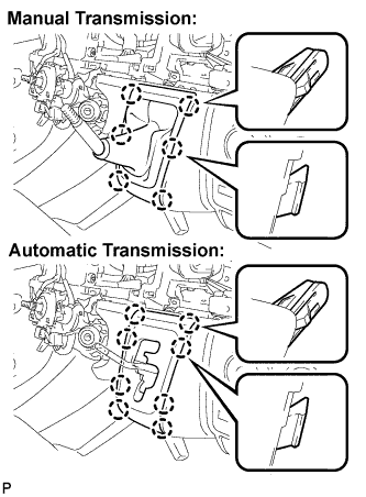
Manual Transmission:
Engage the 6 claws and install the shifting hole cover assembly.
-
Automatic Transmission:
Engage the 8 claws and install the sifting hole cover assembly.
-
-
INSTALL SHIFT LEVER KNOB
-
INSTALL PARKING BRAKE HOLE COVER
-
Engage the 6 claws and install the parking brake hole cover.
-
-
INSTALL INSTRUMENT PANEL UNDER COVER SUB-ASSEMBLY NO.1
-
Engage the 3 claws.
-
Install the instrument panel No.1 under cover sub-assembly with the 2 clips.
-
-
INSTALL INSTRUMENT PANEL FINISH PANEL LOWER
-
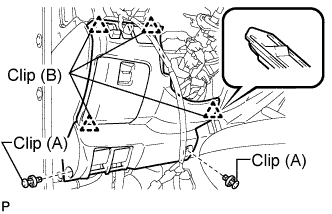
Engage the 4 clips (B).
-
Install the instrument panel finish panel lower with the 2 clips (A).
-
-
CONNECT CABLE TO NEGATIVE BATTERY TERMINAL
-
PERFORM INITIALIZATION
Some systems need initialization after reconnecting the cable to the negative battery terminal. Click here