CLUTCH PEDAL INSTALLATION

-
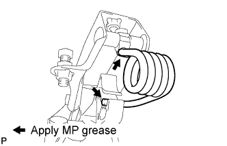
INSTALL CLUTCH PEDAL SPRING HOLDER
-
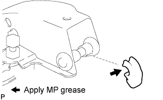
Apply MP grease to the inside of a new clutch pedal spring holder.
-
Install the clutch pedal spring holder.
-
-
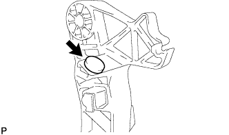
INSTALL CLUTCH PEDAL PAD
-
Install the clutch pedal pad to the clutch pedal.
-
-
INSTALL CLUTCH PEDAL NO.1 CUSHION
-
Using needle-nose pliers, install the clutch pedal No.1 cushion to the clutch pedal.
-
-
INSTALL CLUTCH PEDAL SHAFT COLLAR
-
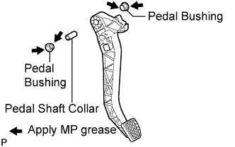
Apply MP grease to the inner, outer and end surfaces of 2 new pedal bushings.
-
Install the clutch pedal shaft collar and 2 pedal bushings to the clutch pedal.
-
-
INSTALL CLUTCH PEDAL SUB-ASSEMBLY
-
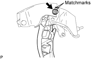
Align the matchmarks on the clutch pedal and clutch pedal support.
-
Install the clutch pedal to the clutch pedal support with the pedal shaft, washer, and nut.
- Torque:
- 34 N*m { 350 kgf*cm, 25 ft.*lbf }
-
-
INSTALL TURNOVER SPRING SEAT COMPRESSION SPRING
-
Apply MP grease to the sliding portion of the spring.
-
Install the turn over spring seat compression spring.
-
-
INSTALL CLUTCH PEDAL SPRING (2KD-FTV ENGINE TYPE)
-
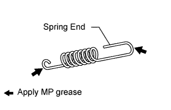
Apply MP grease No.2 to the sliding portion of the spring.
-
Install the clutch pedal spring.
Note
Be sure to install the spring with its end facing upward.
-
Install a new E-ring.
-
-
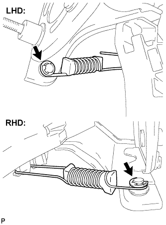
INSTALL CLUTCH PEDAL SUPPORT SUB-ASSEMBLY
-
Aligning the clip (clutch pedal support side) with the hole of the bracket on the vehicle, install the clutch pedal support.
Note
Make sure that the clip (clutch pedal support side) is securely engaged in the hole of the bracket on the vehicle.
-
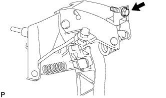
Install the clutch pedal support with the bolt.
- Torque:
- 31 N*m { 316 kgf*cm, 23 ft.*lbf }
-
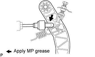
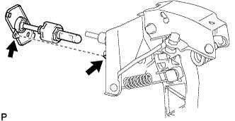
Apply MP grease to the sliding portions of the push rod clevis and clutch pedal.
-
Install the push rod clevis to the cutout of the pedal from the right side of the vehicle and push it downward.
Note
Check that the push rod cannot be turned 30° or more in order to confirm that the clevis is securely engaged in the pedal.
-
-
INSTALL CLUTCH MASTER CYLINDER ASSEMBLY
-
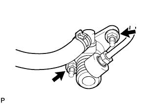
Install the clutch master cylinder with the 2 nuts.
- Torque:
- 14 N*m { 145 kgf*cm, 10 ft.*lbf }
-
-
INSPECT AND ADJUST CLUTCH PEDAL HEIGHT
-
INSTALL AIR DUCT NO.1 (for RHD)
-
INSTALL WASHER TANK AND PUMP ASSEMBLY (for LHD)
-
INSTALL INSTRUMENT PANEL FINISH PANEL LOWER CENTER
-
Engage the 8 claws and install the instrument panel finish panel lower center.
-
-
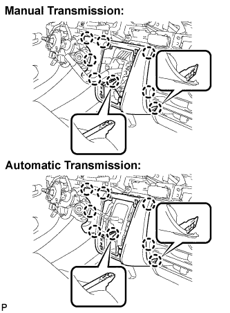
INSTALL SHIFTING HOLE COVER ASSEMBLY
-
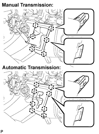
Manual Transmission:
Engage the 6 claws and install the shifting hole cover assembly.
-
Automatic Transmission:
Engage the 8 claws and install the sifting hole cover assembly.
-
-
INSTALL SHIFT LEVER KNOB
-
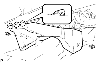
INSTALL PARKING BRAKE HOLE COVER
-
Engage the 6 claws and install the parking brake hole cover.
-
-
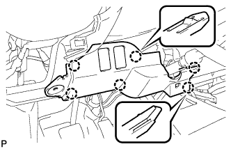
INSTALL INSTRUMENT PANEL UNDER COVER SUB-ASSEMBLY NO.1
-
Engage the 3 claws.
-
Install the instrument panel No.1 under cover sub-assembly with the 2 clips.
-
-
INSTALL INSTRUMENT PANEL FINISH PANEL LOWER
-
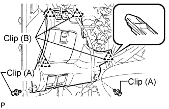
Engage the 4 clips (B).
-
Install the instrument panel finish panel lower with the 2 clips (A).
-
-
CONNECT BATTERY NEGATIVE CABLE
-
PERFORM INITIALIZATION
Some systems need initialization when disconnecting the cable from the negative battery terminal. Click here