SHIFT LEVER ASSEMBLY INSTALLATION

-
INSTALL SHIFT LOCK CONTROL UNIT ASSEMBLY
-
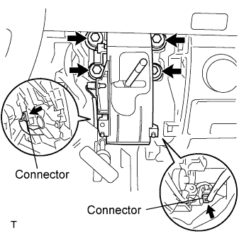
Install the shift lock control unit assembly with the 4 bolts.
- Torque:
- 14 N*m { 140 kgf*cm, 10 ft.*lbf }
-
Install the shift lock computer connector and the indicator light wire connector.
-
-
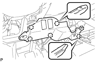
INSTALL TRANSMISSION CONTROL CABLE ASSEMBLY
-
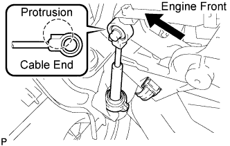
Connect the cable end to the shift lock control unit.
Note
-
Securely connect the cable end until if fits securely against the base of the pin.
-
Connect the cable end with the protrusion facing the front of the vehicle.
-
-
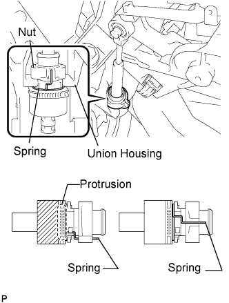
Turn the nut on the transmission control cable counterclockwise unit it stops it in place.
-
Connect the transmission control cable to the shift lock control unit housing.
Note
-
Connect the cable outer with the protrusion on the bottom.
-
Ensure that the groove on the cable outer is securely fitted to the shift lock control unit housing.
-
Ensure that the spring is positioned as show in the illustration.
-
-
-
INSTALL INSTRUMENT PANEL FINISH PANEL LOWER CENTER
-
Engage the 8 claws and install the instrument panel finish panel lower center.
-
-
INSTALL PARKING BRAKE HOLE COVER
-
Engage the 6 claws and install the parking brake hole cover.
-
-
INSTALL INSTRUMENT PANEL FINISH PANEL LOWER
-
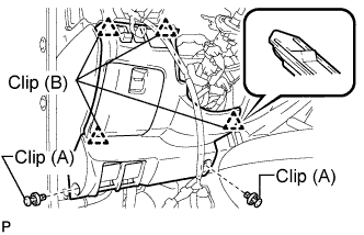
Engage the 4 clips (B).
-
Install the instrument panel finish panel lower with the 2 clips (A).
-
-
INSTALL INSTRUMENT PANEL UNDER COVER SUB-ASSEMBLY NO.1
-
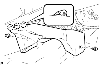
Engage the 3 claws.
-
Install the instrument panel No.1 under cover sub-assembly with the 2 clips.
-
-
INSTALL SHIFT LOCK RELEASE BUTTON
-
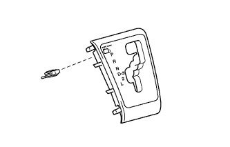
Install the shift lock release button to the shift position indicator housing.
-
-
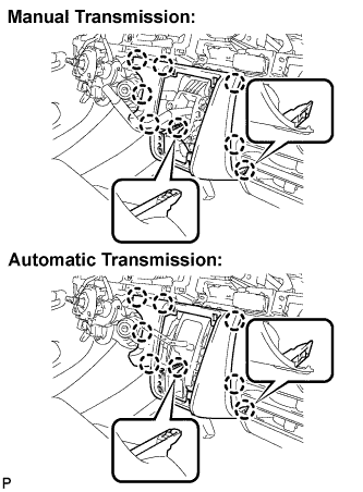
INSTALL SHIFT POSITION INDICATOR HOUSING SUB-ASSEMBLY
-
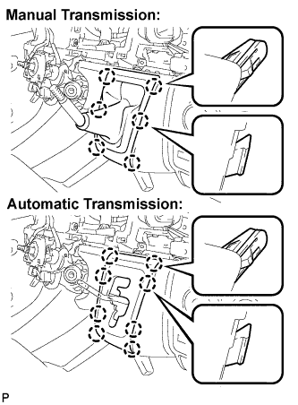
Manual Transmission:
Engage the 6 claws and install the shifting hole cover assembly.
-
Automatic Transmission:
Engage the 8 claws and install the sifting hole cover assembly.
-
-
INSTALL SHIFT LEVER KNOB
-
CONNECT BATTERY NEGATIVE CABLE
-
INSPECT SHIFT LEVER POSITION
-
When shifting from P position only with ignition switch ON and depress the break pedal.
-
Make sure that the shifting lever moves smoothly and can be moderately operated.
-
When starting engine, make sure that the vehicle moves forward when shifting from N to D position and moves reward when shifting R position.
-
-
ADJUST SHIFT LEVER POSITION
-
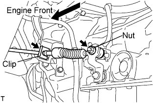
Remove a clip, nut, and disconnect between the control shaft lever to transmission control cable assembly from the control shaft lever and transmission control cable bracket No.1.
-
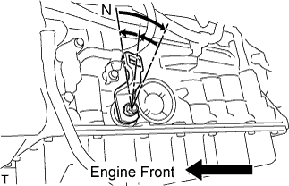
Turn the control shaft lever until stop to a clockwise direction, return the control shaft lever 2 notches to N position.
-

Set the shift lever to N position while holding the shift lever lightly toward the R position side and install it.
- Torque:
- 15 N*m { 150 kgf*cm, 11 ft.*lbf }
Note
Tighten the nut with it closing up cranky.
-
Inspect the operation condition and work.
-
-
PERFORM INITIALIZATION