WATER PUMP INSTALLATION

-
INSTALL WATER PUMP ASSEMBLY
-
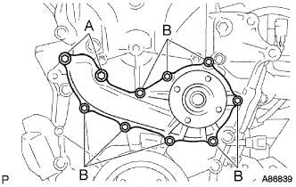
Install a new gasket and the water pump assembly with the 10 bolts.
- Torque:
- Bolt (A)
- 21 N*m { 214 kgf*cm, 15 ft.*lbf }
- Bolt (B)
- 9.0 N*m { 92 kgf*cm, 80 in.*lbf }
-
-
INSTALL VANE PUMP ASSEMBLY
-
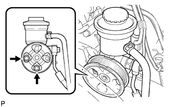
Install the vane pump with the 2 bolts.
- Torque:
- 21 N*m { 214 kgf*cm, 15 ft.*lbf }
-
Connect the PS fluid pressure switch connector.
-
-
INSTALL V-RIBBED BELT TENSIONER ASSEMBLY
-
INSTALL GENERATOR ASSEMBLY
-
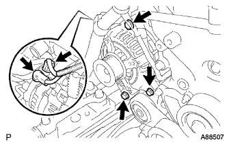
Install the generator assembly with the 3 bolts.
- Torque:
- 43 N*m { 438 kgf*cm, 32 ft.*lbf }
-
Install the generator wire with the nut to terminal B.
- Torque:
- 9.8 N*m { 100 kgf*cm, 87 in.*lbf }
-
Install the terminal cap.
-
Connect the generator connector.
-
-
INSTALL FAN PULLEY
-
Install the fan spacer and fan pulley with the 4 nuts.
- Torque:
- 25 N*m { 255 kgf*cm, 18 ft.*lbf }
-
-
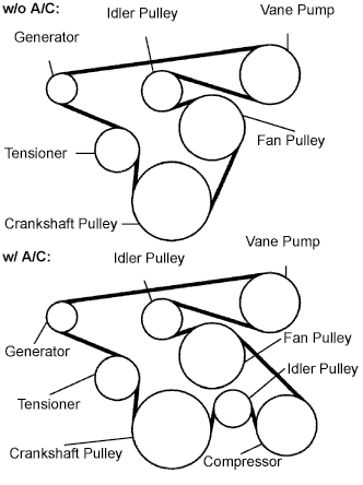
INSTALL FAN & GENERATOR V BELT
-
Install the drive belt to the pulleys except the drive belt tensioner pulley.
-
Use the hexagon-shaped part indicated by the arrow in the illustration to move the tensioner pulley downward and then install the drive belt to the tensioner pulley.
Note
-
The backside of the drive belt should face the tensioner pulley.
-
Check that the drive belt is properly set to each pulley.
-
-
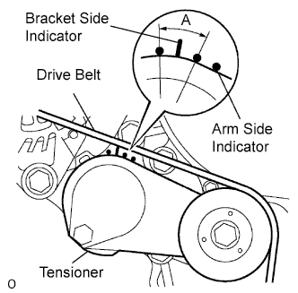
After a new belt has been installed, check that the tensioner indicator mark is within range A shown in the illustration.
-
-
INSTALL INTAKE AIR CONNECTOR
-
Temporarily install the intake air connector to the throttle body assembly.
-
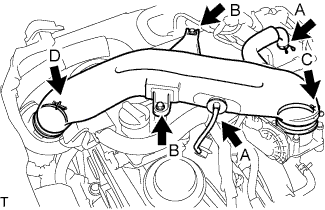
Connect the ventilation hose No.2 and the vacuum hose. (A)
-
Install the intake air connector with the 2 bolts. (B)
- Torque:
- 8.0 N*m { 82 kgf*cm, 71 in.*lbf }
-
Tighten the 2 hose clamp bolts. (C)
- Torque:
- 5.0 N*m { 51 kgf*cm, 44 in.*lbf }
-
Tighten the 2 hose clamp bolts. (D)
-
-
INSTALL ENGINE SERVICE HOLE SUB COVER SUB-ASSEMBLY
-
Install the engine service hole sub cover with the 5 bolts.
- Torque:
- 13 N*m { 133 kgf*cm, 10 ft.*lbf }
-
-
INSTALL FRONT SEAT ASSEMBLY RH (for Hi-back Seat Type)
Tech Tips
Use the same procedures described for the LH side. Click here
-
INSTALL FRONT SEAT ASSEMBLY RH (for Low-back Seat Type)
Tech Tips
Use the same procedures described for the LH side. Click here
-
INSTALL FRONT DOOR SCUFF PLATE RH
-
CONNECT CABLE TO NEGATIVE BATTERY TERMINAL
-
ADD ENGINE COOLANT
-
Firmly tighten the drain plugs and fill the reservoir tank with coolant to the top of the inlet.
-
Remove the 2-way that is located near the throttle body.
-
When air is bled and the coolant drains out, firmly install the 2-way.
-
Add coolant up to the B line mark in the reservoir tank and install the radiator cap.
Coolant Capacity Condition Capacity w/ front and rear heaters 13.6 liters (14.4 US qts, 12.0 lmp. qts) w/ front heater 11.6 liters (12.3 US qts, 10.2 lmp. qts) w/o heater 10.6 liters (11.2 US qts, 9.3 lmp. qts) -
Warm up the engine.
-
After the engine cools down, check that the coolant level is between the LOW and FULL level marks.
-
-
CHECK FOR ENGINE COOLANT LEAKS
CAUTION:
Do not remove the radiator cap while the engine and radiator are still hot. Pressurized, hot engine coolant and steam may be released and cause serious burns.
-
Fill the radiator with coolant and attach a radiator cap tester to the radiator.
-
Warm up the engine.
-
Using a radiator cap tester, increase the pressure inside the radiator to 137 kPa (1.4 kgf/cm2, 19.9 psi), and check that the pressure does not drop.
Tech Tips
If the pressure drops, check the hoses, radiator or water pump for leaks. If no external leaks are found, check the heater core, cylinder block and cylinder head.
-
-
INSTALL ENGINE UNDER COVER NO.1
-
PERFORM INITIALIZATION
Some systems need initialization when reconnecting the battery cable. Click here