ELECTRIC EGR CONTROL VALVE (w/o DPF) INSTALLATION

-
TEMPORARILY TIGHTEN ELECTRIC EGR CONTROL VALVE ASSEMBLY
-
Temporarily tighten the electric EGR control valve.
-
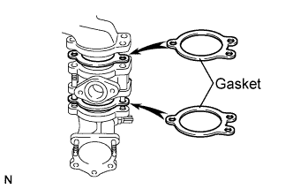
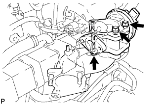
Install 2 new gaskets and the electric EGR control valve onto the intake air connector as shown in the illustration.
-
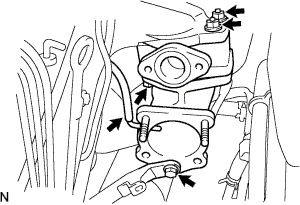
Temporarily tighten the intake air connector with electric EGR control valve to the intake manifold with the bolt and the 2 nuts.
-
Install the vacuum hose onto the intake air connector.
-
Temporarily tighten the manifold stay with the bolt.
-
-
-
TEMPORARILY TIGHTEN EGR COOLER ASSEMBLY

-
Temporarily tighten the EGR cooler assembly.
-
Temporarily tighten the EGR cooler assembly and new gaskets.
-
Temporarily tighten the EGR cooler assembly stay bolt.
-
Tighten the EGR cooler assembly with the 2 nuts and 2 bolts.
- Torque:
- 13 N*m { 133 kgf*cm, 10 ft.*lbf }
-
-
-
TIGHTEN ELECTRIC EGR CONTROL VALVE ASSEMBLY
-
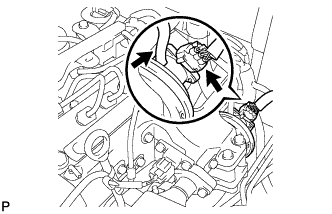
Tighten the electric EGR control valve with the bolt and 2 nuts.
- Torque:
- 20 N*m { 204 kgf*cm, 15 ft.*lbf }
-
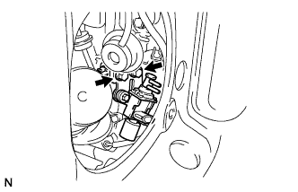
Connect the intake air temperature sensor connector.
-
Connect the vacuum hose to the electric EGR control valve.
-
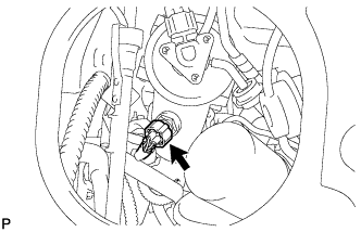
Connect the electric EGR control valve connector.
-
Install the vacuum regulating valve with bracket with the 2 bolts.
- Torque:
- 20 N*m { 204 kgf*cm, 15 ft.*lbf }
-
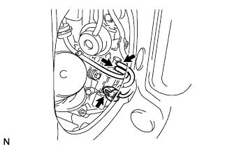
Connect the 2 vacuum hoses to the vacuum regulating valve.
-
Connect the vacuum regulating valve connector.
-
-
TIGHTEN EGR COOLER ASSEMBLY
-
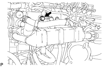
Tighten the EGR cooler assembly stay bolt.
- Torque:
- 22 N*m { 224 kgf*cm, 16 ft.*lbf }
-
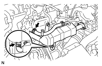
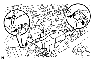
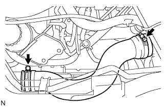
Install the No. 2 water by-pass hose with the clip.
-
Install the No. 4 water by-pass hose with the clip.
-
-
INSTALL MANIFOLD STAY
-
Tighten the manifold stay bolt.
- Torque:
- 19 N*m { 194 kgf*cm, 14 ft.*lbf }
-
-
INSTALL DIESEL THROTTLE BODY ASSEMBLY
Note
After removing and installing, or replacing the throttle body, be sure to perform the operation check.
-
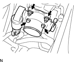
Install a new gasket onto the intake air connector.
-
Install the throttle body with the 2 bolts and the 2 nuts.
- Torque:
- 20 N*m { 204 kgf*cm, 15 ft.*lbf }
-
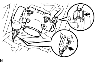
Connect the 2 throttle body connectors.
-
-
INSTALL NO. 4 AIR HOSE
-
Install the No. 4 air hose with the 2 clamps.
- Torque:
- 6.0 N*m { 61 kgf*cm, 53 in.*lbf }
-
-
CONNECT OIL RETURN HOSE
-
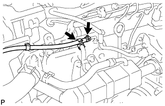
Connect the oil return hose with the 2 clips.
-
-
INSTALL VANE PUMP OIL RESERVOIR ASSEMBLY
-
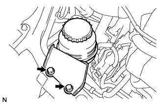
Install the vane pump oil reservoir assembly with the 2 bolts.
- Torque:
- 8.0 N*m { 82 kgf*cm, 71 in.*lbf }
-
-
INSTALL NO. 2 ENGINE SERVICE HOLE COVER
-
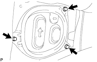
Install the No. 2 engine service hole cover with the 3 bolts.
-
-
CONNECT CABLE TO NEGATIVE BATTERY TERMINAL
- Torque:
- 5.4 N*m { 55 kgf*cm, 48 in.*lbf }
-
ADD ENGINE COOLANT
-
Firmly tighten the drain plugs.
-
Fill the radiator reserve tank assembly with coolant to the top of the inlet.
Coolant capacity Condition Capacity w/ rear heater 18.2 liters (19.2 US qts, 16.0 lmp. qts) w/o rear heater 16.2 liters (17.0 US qts, 14.0 lmp. qts) Note
Do not substitute plain water for engine coolant.
Tech Tips
-
Use of improper coolants may damage the engine cooling system.
-
Use only Toyota Super Long Life Coolant or similar high quality ethylene glycol based non-silicate, non-amine, non-nitrite, and non-borate coolant with long-life hybrid organic acid technology (coolant with long-life hybrid organic acid technology consists of a combination of low phosphates and organic acids).
-
-
Loosen the bleeder plug of the outlet housing.
-
When air is bled and the coolant drains out, firmly install the bleeder plug.
-

Add coolant up to the B line mark in the radiator reserve tank assembly and install the radiator cap.
-
Warm up the engine until the thermostat opens.
-
While the thermostat is open, circulate the coolant for several minutes.
Tech Tips
The thermostat open timing can be confirmed by pressing the inlet radiator hose by hand, and checking when the engine coolant starts to flow inside the hose.
-
-

After the engine cools down, check that the coolant level is between the LOW and FULL level marks.
-
-
INSPECT FOR ENGINE COOLANT LEAK
-
INSPECT FOR EXHAUST GAS LEAK
-
PERFORM INITIALIZATION
-
Perform initialization procedures Click here.
Note
Certain systems need to be initialized after reconnecting the cable to the negative (-) battery terminal.
-