ECD SYSTEM (w/o DPF) Lack of Power or Hesitation
DESCRIPTION
| Malfunction Condition | Main Trouble Area | Related Trouble Area |
|---|---|---|
|
(a) Injector assembly malfunctions
(b) Abnormal common rail pressure
(c) Abnormal intake air volume
|
|
Tech Tips
-
Specified values in the following troubleshooting flowchart are for reference only. Variations in the Data List values may occur depending on the measuring conditions or the vehicle's age. Do not judge the vehicle to be normal even when the Data List values indicate a standard level. There are possibly some concealed factors causing the malfunction.
-
Check that the vehicle has not been modified in any way prior to the vehicle inspection.
-
This troubleshooting procedure checks for the cause of an obvious lack of engine power while the vehicle is being driven (such as the maximum speed being extremely low).
-
Faults and Symptoms of Common Rail Diesel Components
-
Engine Control
Mass Air Flow Meter Main fault Decrease in performance (foreign matter is stuck) Symptoms Lack of power, black smoke Data List MAF Tech Tips
The maximum fuel injection volume is controlled according to the output from the mass air flow meter.
Intake System Symptom and Corresponding Main Fault
-
Lack of power (no black smoke) due to air filter blockage or crushed or leaking air duct
-
Black smoke (no lack of power) due to leakage between the turbo and intake manifold
Data List
-
MAP
-
Target Booster Pressure
When the accelerator is fully depressed, if MAP is 20 kPa lower than Target Booster Pressure for more than 5 seconds, then a lack of power will be felt.
-
MAF
Turbocharger System Main fault
-
Air leak in the turbocharged air passage
-
Turbocharger (turbine, bearing, variable nozzle)
Symptoms Lack of power (when vehicle is starting, under heavy load)
(Black smoke is not emitted when racing while vehicle is stopped)
Data List MAP, Target Booster Pressure
-
When the accelerator is fully depressed, if MAP is 20 kPa lower than Target Booster Pressure for more than 5 seconds, then a lack of power will be felt.
-
With the ignition switch to ON or during idling, MAP = atmospheric pressure (standard atmospheric pressure = 101 kPa). When the engine speed is about 1500 rpm or more, the turbocharger starts to take effect and MAP becomes higher than atmospheric pressure.
-
Atmospheric pressure decreases by 1 kPa each time elevation increases by 100 m, and is also affected by the current weather conditions.
Exhaust System Main fault Blockage Symptoms Lack of power (high engine speed, under heavy load) Data List MAP, Target Booster Pressure
When the accelerator is fully depressed, if MAP is 20 kPa lower than Target Booster Pressure for more than 5 seconds, then a lack of power will be felt.
Glow System Main fault Open circuit, glow plug relay fault Symptoms Difficult to start, rough idle, knocking, white smoke (when cold) Data List Check the glow plug indicator light Diagnostic Point Measure the resistance of the glow plug Engine - 1 Main fault Damaged, seized up Symptoms Cannot crank, crank speed is low, strange noise Engine - 2 Main fault Loss of compression Symptoms Rough idle (lack of power always) Data List Engine Speed of Cyl#
-
When cranking during the "Check the Cylinder Compression" Active Test, if there is a high speed cylinder, approx. 100 rpm more than the other cylinders, that cylinder may lose compression.
Injection Feedback Val
-
When an Injector Feedback Val is more than 3 mm3/st, there may be a malfunction in the corresponding cylinder.
-
-
Diesel Injection
Fuel Supply Pump Assembly Main fault - Symptoms Difficult to start, engine stalling, rough idle, lack of power Data List Fuel Press, Target Common Rail Pressure
-
Fuel Press is within 5000 kPa of Target Common Rail Pressure during idling with the engine warmed up (engine coolant temperature is higher than 70°C (158°F)).
-
If the fuel pressure is 20000 kPa below the target pressure, then a lack of power will be felt.
-
If the fuel pressure is below 25000 kPa, then idling will be rough.
Tech Tips
-
The fuel pressure changes at engine start, but is approx. 25000 kPa at engine start after the engine is warmed up.
Diagnostic Trouble Code Even if Fuel Press is below Target Common Rail Pressure, a DTC will not be stored. Fuel Filter Element Sub-assembly Main fault Blockage Symptoms Difficult to start, engine stalling, rough idle, lack of power Data List Fuel Press, Target Common Rail Pressure
-
Fuel Press is within 5000 kPa of Target Common Rail Pressure during idling with the engine warmed up (engine coolant temperature is higher than 70°C (158°F)).
-
If the fuel pressure is 20000 kPa below the target pressure, then a lack of power will be felt.
-
If the fuel pressure is below 25000 kPa, then idling will be rough.
Tech Tips
The fuel pressure changes at engine start, but is approx. 25000 kPa at engine start after the engine is warmed up.
Diagnostic Trouble Code Even if Fuel Press is below Target Common Rail Pressure, a DTC will not be stored. Injector Assembly Main fault Blockage Symptoms Rough idle, lack of power, black smoke, white smoke, knocking Data List Injection Feedback Val
-
When an Injector Feedback Val is more than 3 mm3/st, there may be a malfunction in the corresponding cylinder. This value can be read after idling for 1 minute.
Injector Driver Main fault Circuit fault: The injector assembly does not open. Symptoms Difficult to start, rough idle, lack of power, black smoke, white smoke, knocking Data List Same as injector assembly Diagnostic Trouble Code When the injector driver has a fault, some DTCs may be stored. Fuel Pressure Sensor Main fault Open circuit, decrease in performance (foreign matter is stuck) Symptoms Difficult to start, rough idle, engine stall, lack of power Data List Fuel Press, Target Common Rail Pressure
-
Fuel Press is within 5000 kPa of Target Common Rail Pressure during idling with the engine warmed up (engine coolant temperature is higher than 70°C (158°F)).
-
Slowly raise the engine speed from idling to 3000 rpm with the vehicle stopped and check that Fuel Press and Common Rail Pres Sens 2 follow Target Common Rail Pressure. If the fuel pressure sensor malfunctions, the actual fuel pressure may deviate from the target fuel pressure (either Fuel Press or Common Rail Pres Sens 2 decreases to a value less than Target Common Rail Pressure).
Diagnostic Code When the fuel pressure sensor has a fault, some DTCs may be stored. Irregular Fuel Main fault - Symptoms Difficult to start, rough idle (especially when cold) -
-
Diesel EGR
EGR System Main fault
-
Does not move smoothly
-
Does not close fully
Symptoms
-
Rough Idle
-
EGR valve stuck closed: A loud turbocharger sound.
-
EGR valve stuck open: Difficult to start (does not stall), black smoke, white smoke (when engine is cold), lack of power, jerking (If there is an excess in the quantity of EGR and there is a heavy load, when the vehicle starts moving, a lack of power will be felt. Also, when racing the engine, there will be some black smoke).
Data List Actual EGR Valve Pos., Target EGR Position
-
Generally, Actual EGR Valve Pos. = Target EGR Pos. +/-5% (fully closed: 0%, fully open: 100%).
-
Using the EGR valve Active Test, check whether Actual EGR Valve Pos. follows Target EGR Position (the engine coolant temperature and intake air temperature should be considered when a malfunction occurs).
-
EGR valve is fully closed when the ignition switch is ON (engine stopped).
-
EGR valve opens to the halfway point at idling after the engine is warmed up.
-
When the EGR valve does not close, MAF (Mass Air Flow) decreases when the vehicle is accelerated at full throttle. MAP also decreases in comparison to Target Booster Pressure, however there is not a large difference.
EGR Close Lrn. Val., EGR Close Lrn. Status
-
When leaving the vehicle idling, when EGR Close Lrn. Status is OK, the normal range of EGR Close Lrn. Val. is 3.75 to 4.8 V.
-
In cases when EGR Close Lrn. Status. is NG or EGR Close Lrn. Val. is out of the normal range (3.75 to 4.8 V), it is possible that the EGR valve cannot completely close.
-
-
Diesel Throttle
Diesel Throttle System Main fault Stuck, does not move smoothly Symptoms
-
Stuck closed: Lack of power, difficult to start, rough idle, engine stall, black smoke. These may occur when stuck almost fully closed.
-
Stuck open: Turbocharger sound increases. When the engine is stopped, engine vibrations may occur.
Data List
-
Actual Throttle Position (fully closed: 100%, fully open: 0%)
-
When the ignition switch is ON (engine stopped), the diesel throttle is fully open. When idling, the diesel throttle is at the halfway point. When the ignition switch is turned from ON to off, the throttle is fully closed temporarily.
-
-
-
Data List Related to Lack of Power
-
Engine Speed
-
MAP
-
MAF
-
Intake Air
-
Coolant Temp
-
Target Common Rail Pressure
-
Fuel Press
-
Target Pump SCV Current
-
Injection Feedback Val #1 (to #4)
-
Injection Volume
-
Actual Throttle Position
-
Target EGR Position
-
Actual EGR Valve Pos.
-
INSPECTION PROCEDURE
-
Explanation of Symptom
Lack of Power The power of the diesel engine is determined by the quantity of injected fuel and the quantity of intake air.
The quantity of injected fuel is determined by the fuel pressure and the amount of time the injector assembly is open. Basically, the fuel pressure is controlled so that it reaches the target fuel pressure. The throttle valve does not restrict air flow volume, so the manifold absolute pressure is almost the same as atmospheric pressure when idling. At more than approximately 1500 rpm, the turbo starts to operate causing the manifold absolute pressure to become higher than atmospheric pressure.
The manifold absolute pressure is controlled so that it reaches the Target Booster Pressure when accelerating the vehicle at full throttle. Also, when accelerating the vehicle at full throttle, the throttle is fully open and the EGR valve is fully closed, preserving the mass air flow.
Note
-
After replacing the ECM, the new ECM needs registration Click here and initialization Click here.
-
After replacing the fuel supply pump assembly, the ECM needs initialization Click here.
-
After replacing an injector assembly, the ECM needs registration Click here.
-
PROCEDURE
-
READ OUTPUT DTC (RELATING TO ENGINE)
-
Connect the intelligent tester to the DLC3.
-
Turn the ignition switch to ON and turn the tester on.
-
Enter the following menus: Powertrain / Engine and ECT / DTC.
-
Read pending DTCs.
Result Result Proceed to No DTCs are output A Engine related DTCs are output B
B 
GO TO DTC CHART Click here
A 
-
-
TAKE SNAPSHOT DURING IDLING AND 4000 RPM (PROCEDURE 2)
-
Connect the intelligent tester to the DLC3.
-
Start the engine and turn the tester on.
-
Enter the following menus: Powertrain / Engine and ECT / Data List / Lack of power.
-
With no load after the engine is warmed up, take a snapshot when idling and at 4000 rpm.
Tech Tips
-
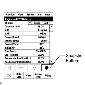
A snapshot can be used to compare vehicle data from the time of the malfunction to normal data and is very useful for troubleshooting.
-
Graphs can be displayed by transferring the stored snapshot data from the tester to a PC. Intelligent Viewer must be installed on the PC.
-
The shift lever should be in neutral and the A/C switch and all accessory switches should be off.
Data of Normal Vehicle Recorded after Engine Warmed up with A/C Off while Running Engine at 4000 rpm without Load and while Idling Data List Reference Values Recorded while Running Engine at 4000 rpm without Load Reference Values Recorded while Idling Unit Vehicle Speed 0 0 km/h Engine Speed 3995 700 rpm Accel Position 16.40 0.00 % Calculate Load 35.2 16.4 % MAF 106.48 8.64 gm/s MAP 117 97 kPa Atmosphere Pressure 100 100 kPa Coolant Temp 82 83 °C Intake Air 45 38 °C Fuel Press 87660 34870 kPa Target Pump SCV Current 1169.0 1030.0 mA Injection Volume 16.5 8.8 mm3/st
Injection Feedback Val #1 -0.4 -0.5 mm3/st
Injection Feedback Val #2 -0.2 -0.2 mm3/st
Injection Feedback Val #3 0.3 0.1 mm3/st
Injection Feedback Val #4 -0.4 0.1 mm3/st
Actual Throttle Position 0.0 81 % Target EGR Position 0.0 57.6 % EGR Lift Sensor Volt % 14.4 51.1 % VN Turbo Command 52 90 % Tech Tips
The above values were measured under standard atmospheric pressure. The values are influenced by elevation, weather conditions, etc.
Standard atmospheric pressure is 101 kPa. For every 100 m increase in elevation, pressure drops by 1 kPa. This varies by weather.
-
NEXT
-
-
TAKE SNAPSHOT DURING LACK OF POWER (PROCEDURE 3)
-
Connect the intelligent tester to the DLC3.
-
Start the engine and turn the tester on.
-
Enter the following menus: Powertrain / Engine and ECT / Data List / All Data.
-
Take a snapshot of the following Data List items with the intelligent tester during lack of power.
Tech Tips
-
A snapshot can be used to compare vehicle data from the time of the malfunction to normal data and is very useful for troubleshooting.
-
Graphs can be displayed by transferring the stored snapshot data from the tester to a PC. Intelligent Viewer must be installed on the PC.
-
Move the shift lever to 2nd gear and accelerate the vehicle with the accelerator pedal fully depressed (obey all laws and regulations, and pay attention to traffic conditions while driving the vehicle). Then, check the Data List with the engine warmed up and idling (the shift lever should be in neutral and the A/C switch and all accessory switches should be off).
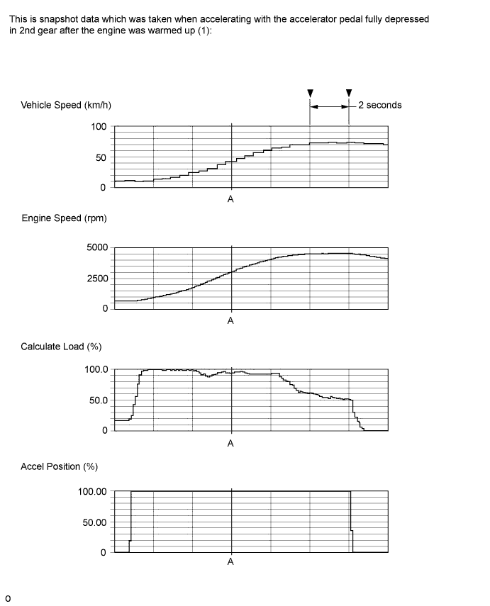
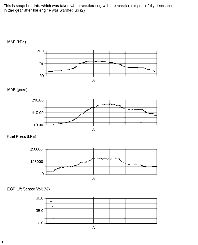
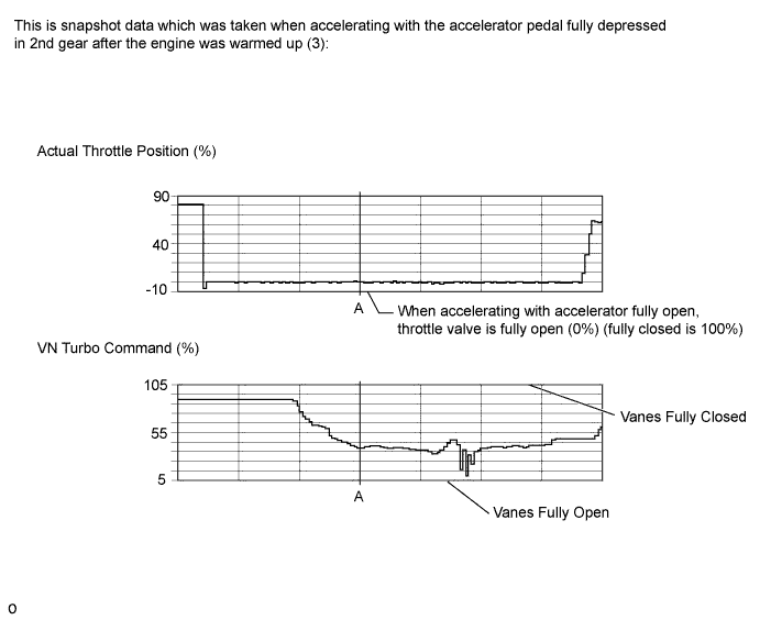
Reference Values with Engine Speed at 3000 rpm (Point A) Data List Value Unit Vehicle Speed 43 km/h Engine Speed 3093 rpm Accel Position 99.60 % Calculate Load 94.1 % MAF 149.70 gm/s MAP 197 kPa Atmosphere Pressure 99 kPa Coolant Temp 85 °C Intake Air 34 °C Fuel Press 159070 kPa Target Pump SCV Current 1568.0 mA Injection Volume 87.6 mm3/st
Injection Feedback Val #1 -0.8 mm3/st
Injection Feedback Val #2 0.9 mm3/st
Injection Feedback Val #3 0.0 mm3/st
Injection Feedback Val #4 -0.5 mm3/st
Actual Throttle Position 0 % Target EGR Position 0.0 % EGR Lift Sensor Volt % 12.8 % VN Turbo Command 39 % Tech Tips
-
Examples of actual malfunctions (See "Diagnostic Help" menu):
-
Lack of power caused by overly low boost pressure
-
Lack of power caused by overly low MAF
-
EGR valve stuck in open position
-
For engine protection, exhaust gas or fuel economy related reasons, there are some ranges of engine operation where engine power feels like it flattens out, but this is not a malfunction.
-
The above values were measured under standard atmospheric pressure. The values are influenced by elevation, weather conditions, etc.
Standard atmospheric pressure is 101 kPa. For every 100 m increase in elevation, pressure drops by 1 kPa. This varies by weather.
-
The engine speed must be 1500 rpm or less before performing the inspection in which the accelerator pedal is fully depressed and the engine is accelerated to a speed of 3000 rpm.
-
-
Check for a lack of power during the driving test.
Result Result Proceed to Apparent lack of power is present A Apparent lack of power is not present B
B 
COMPARE WITH SIMILAR VEHICLE WITH SAME ENGINE Click here
A
-
-
CHECK SNAPSHOT (MAP AND MAF)
-
Check MAP and MAF in the snapshot taken in procedure 2 when the engine was running at 4000 rpm with no load.
Result Result Proceed to MAP is 110 kPa or higher and MAF is 100 gm/s or more*1 A MAP is below 90 kPa*2 B Except above*3 C Tech Tips
The above values were measured under standard atmospheric pressure. The values are influenced by elevation, weather conditions, etc.
Standard atmospheric pressure is 101 kPa. For every 100 m increase in elevation, pressure drops by 1 kPa. This varies by weather.
*1: There may be a problem in the fuel injection system or intake system.
*2: There may be a problem in the turbocharger system.
*3: There may be a problem in the intake system or a problem with the EGR valve (valve stuck open or valve does not close).
B
READ VALUE USING INTELLIGENT TESTER (MAP AND ATMOSPHERIC PRESSURE) Click here
C
CHECK AIR INTAKE SYSTEM Click here
A
-
-
CHECK SNAPSHOT (FUEL PRESS, TARGET COMMON RAIL PRESSURE, MAP AND TARGET BOOSTER PRESSURE)
-
Check Fuel Press, Target Common Rail Pressure, MAP and Target Booster Pressure in the snapshot taken in procedure 3 when the vehicle was accelerating with the accelerator pedal fully depressed in 2nd gear.
Result Result Proceed to MAP is below 204 kPa at an engine speed of 3000 rpm A Difference between Fuel Press and Target Common Rail Pressure is 20000 kPa or more B Except above C Tech Tips
-
The above values were measured under standard atmospheric pressure. The values are influenced by elevation, weather conditions, etc.
Standard atmospheric pressure is 101 kPa. For every 100 m increase in elevation, pressure drops by 1 kPa. This varies by weather.
-
The engine speed must be 1500 rpm or less before performing the inspection in which the accelerator pedal is fully depressed and the engine is accelerated to a speed of 3000 rpm.
-
If the turbocharger movement is not smooth, etc., the value of MAP in the snapshot taken during lack of power will not reach the target value.
When the accelerator pedal is fully depressed and the engine speed is 3000 rpm, the MAP should be higher than 185 kPa.
-
B
CHECK IF FUEL IS BEING SUPPLIED TO FUEL SUPPLY PUMP ASSEMBLY Click here
C
CHECK AIR INTAKE SYSTEM Click here
A
-
-
CHECK INTAKE SYSTEM
-
Check for air leaks and blockages between the air cleaner case and turbocharger, and between the turbocharger and intake manifold.
Tech Tips
-
Inspect the air intake system, especially hoses and pipes between the air cleaner and turbocharger.
-
Check for abnormal disconnections, pipe and hose squashing, and any damage in the intake system.
-
Using your hand, check whether the pipes and hoses in the intake system are securely connected.
-
By applying soapy water and revving up the engine, air leaks from the intake system can be checked by checking for bubbles.
-
Check for any modifications in the intake system made by the user.
OK No leakage or blockage. -
NG
REPAIR OR REPLACE AIR INTAKE SYSTEM Click here
OK
-
-
CLEAN FUEL FILTER CASE AND REPLACE FUEL FILTER
-
Clean the fuel filter case and replace the fuel filter.
Tech Tips
Be sure to clean the inside of the fuel filter case as the fuel injectors may not operate properly if the fuel filter is installed with foreign matter remaining inside the fuel filter case.
NEXT
-
-
REPLACE INJECTOR ASSEMBLIES OF ALL CYLINDERS
-
Replace the injector assemblies Click here.
Note
-
When replacing the injector assembly for a cylinder, always be sure to use a new injection pipe.
-
Follow the procedure in the repair manual and temporarily install the injection pipes and nozzle leakage pipe, and then correctly position the injector assemblies. After that, tighten parts according to the torque specifications.
-
If the installation procedure is not performed correctly, injector assemblies may become out of position, which may cause the injector assemblies to deteriorate, resulting in malfunctions.
-
If an injector assembly deteriorates and malfunctions, other problems such as knocking, rough idle, etc. may occur.
-
If an injector assembly becomes out of position, it is possible that the seal between the injector assembly and injection pipe may become incomplete, resulting in a fuel leak.
-
NEXT
-
-
BLEED AIR FROM FUEL SYSTEM
-
Bleed the air from the fuel system Click here.
NEXT
-
-
REGISTER INJECTOR COMPENSATION CODE AND PERFORM PILOT QUANTITY LEARNING
-
Register the injector compensation code Click here.
-
Perform the injector pilot quantity learning Click here.
NEXT
-
-
CONFIRM WHETHER MALFUNCTION HAS BEEN SUCCESSFULLY REPAIRED
NEXT 
END
-
READ VALUE USING INTELLIGENT TESTER (MAP AND ATMOSPHERIC PRESSURE)
-
Connect the intelligent tester to the DLC3.
-
Turn the ignition switch to ON and turn the tester on.
-
Enter the following menus: Powertrain / Engine and ECT / Data List / MAP and Atmosphere Pressure.
-
Compare MAP to Atmosphere Pressure when the ignition switch is ON (do not start the engine).
Standard Difference between MAP and Atmosphere Pressure is less than 8 kPa. Tech Tips
-
If MAP and Atmosphere Pressure have the same value, both are normal. If there is a difference of 8 kPa or more, compare the values to the atmospheric pressure for that day. The sensor whose deviation is the greatest is malfunctioning.
-
Standard atmospheric pressure is 101 kPa. For every 100 m increase in elevation, pressure drops by 1 kPa. This varies by weather.
Result Result Proceed to MAP and Atmosphere Pressure have same value A MAP is different from actual atmospheric pressure B Atmosphere Pressure is different from actual atmospheric pressure C -
B
REPLACE MANIFOLD ABSOLUTE PRESSURE SENSOR Click here
C
REPLACE ECM Click here
A
-
-
CHECK AIR INTAKE SYSTEM
-
Check for air leaks and blockages between the air cleaner case and turbocharger, and between the turbocharger and intake manifold.
Result Result Proceed to Leaks and/or blockages exist in the intake system A No leaks or blockages in the intake system B Tech Tips
-
Inspect the air intake system, especially hoses and pipes between the air cleaner and turbocharger.
-
Check for abnormal disconnections, pipe and hose squashing, and any damage in the intake system.
-
Using your hand, check whether the pipes and hoses in the intake system are securely connected.
-
When inspecting for a clogged intake system (cause of low MAP), check the following points:
-
Clogged air cleaner
-
Clogged intake hose
-
Diesel throttle valve stuck in closed position
-
Check for any modifications in the intake system made by the user.
-
A
REPAIR OR REPLACE AIR INTAKE SYSTEM Click here
B
-
-
CHECK TURBOCHARGER SUB-ASSEMBLY
-
Check for turbocharger sub-assembly Click here.
NG
REPLACE TURBOCHARGER SUB-ASSEMBLY Click here
OK
-
-
CHECK FOR INTERMITTENT PROBLEMS
-
Check for intermittent problems Click here.
NEXT
CONFIRM WHETHER MALFUNCTION HAS BEEN SUCCESSFULLY REPAIRED Click here
-
-
REPLACE MANIFOLD ABSOLUTE PRESSURE SENSOR
-
Replace the manifold absolute pressure sensor.
NEXT
CONFIRM WHETHER MALFUNCTION HAS BEEN SUCCESSFULLY REPAIRED Click here
-
-
REPLACE ECM
-
Replace the ECM Click here.
NEXT
CONFIRM WHETHER MALFUNCTION HAS BEEN SUCCESSFULLY REPAIRED Click here
-
-
REPAIR OR REPLACE AIR INTAKE SYSTEM
-
Repair or replace the malfunctioning part in the air intake system.
NEXT
CONFIRM WHETHER MALFUNCTION HAS BEEN SUCCESSFULLY REPAIRED Click here
-
-
REPLACE TURBOCHARGER SUB-ASSEMBLY
-
Replace the turbocharger sub-assembly Click here.
NEXT
-
-
CONFIRM WHETHER MALFUNCTION HAS BEEN SUCCESSFULLY REPAIRED
NEXT
END
-
CHECK IF FUEL IS BEING SUPPLIED TO FUEL SUPPLY PUMP ASSEMBLY
-
Disconnect the inlet hose from the fuel supply pump assembly.
-
Operate the priming pump and check that fuel is being supplied to the fuel supply pump assembly.
OK Fuel is properly supplied to the fuel supply pump assembly when the priming pump is operated. Tech Tips
-
When there is a lack of fuel, the fuel pressure drops.
-
Inspect for fuel filter element sub-assembly clogging.
-
-
Reconnect the inlet hose.
NG
REPAIR OR REPLACE CLOGGED FUEL PIPE (INCLUDING FROZEN FUEL) (FUEL TANK - FUEL SUPPLY PUMP) Click here
OK
-
-
REPLACE SUCTION CONTROL VALVE
-
Replace the suction control valve Click here.
NEXT
BLEED AIR FROM FUEL SYSTEM Click here
-
-
REPAIR OR REPLACE CLOGGED FUEL PIPE (INCLUDING FROZEN FUEL) (FUEL TANK - FUEL SUPPLY PUMP)
-
Check and repair or replace the clogged fuel pipe.
NEXT
-
-
BLEED AIR FROM FUEL SYSTEM
-
Bleed the air from the fuel system Click here.
NEXT
-
-
PERFORM FUEL SUPPLY PUMP ASSEMBLY INITIALIZATION
-
Perform fuel supply pump assembly initialization Click here.
NEXT
-
-
CONFIRM WHETHER MALFUNCTION HAS BEEN SUCCESSFULLY REPAIRED
-
Connect the intelligent tester to the DLC3.
-
Start the engine and turn the tester on.
-
Enter the following menus: Powertrain / Engine and ECT / Active Test / Test the Fuel Leak / Data List / Fuel Press, Target Common Rail Pressure.
-
Take a snapshot with the intelligent tester during the Active Test.
Tech Tips
Detailed graphs can be displayed by transferring the stored snapshot from the tester to a PC (personal computer) with Intelligent Viewer installed.
-
Measure the difference between the target fuel pressure (Target Common Rail Pressure) and the actual fuel pressure (Fuel Press) when the "Test the Fuel Leak" Active Test is performed.
Tech Tips
In order to obtain an exact measurement, perform the Active Test 5 times and measure the difference once each time the Active Test is performed.
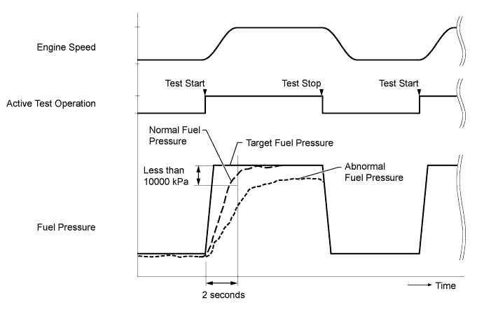
OK The difference between the target fuel pressure and the actual fuel pressure 2 seconds after the Active Test starts is less than 10000 kPa. Tech Tips
-
"Target Common Rail Pressure" is the target fuel pressure controlled by the ECM.
-
"Fuel Press" is the actual fuel pressure.
-
NEXT
END
-
-
CHECK AIR INTAKE SYSTEM
-
Check for air leaks and blockages between the air cleaner case and turbocharger, and between the turbocharger and intake manifold.
Result Result Proceed to No leaks or blockages in the intake system A Leaks and/or blockages exist in the intake system B Tech Tips
-
Inspect the air intake system, especially hoses and pipes between the air cleaner and turbocharger.
-
Check for abnormal disconnections, pipe and hose squashing, and any damage in the intake system.
-
Using your hand, check whether the pipes and hoses in the intake system are securely connected.
-
By applying soapy water and revving up the engine, air leaks from the intake system can be checked by checking for bubbles.
-
Make sure that the hose between the manifold absolute pressure sensor and intake manifold is not loose or disconnected.
-
Check for any modifications in the intake system made by the user.
-
B
REPAIR OR REPLACE AIR INTAKE SYSTEM Click here
A
-
-
PERFORM ACTIVE TEST USING INTELLIGENT TESTER (ACTIVATE THE EGR VALVE CLOSE)
-
Connect the intelligent tester to the DLC3.
-
Enter the engine and warm it up (engine coolant temperature is 70°C (158°F) or higher), and the A/C switch and all accessory switches should be off.
-
Turn the ignition switch off. Wait for 30 seconds and then restart the engine.
-
Turn the tester on.
-
Enter the following menus: Powertrain / Engine and ECT / Data List / MAF.
-
Read the MAF value displayed on the tester when engine idling.
-
Enter the following menus: Powertrain / Engine and ECT / Active Test / Activate The EGR Valve Close.
-
Read the MAF value when the EGR valve is closed using the Active Test function.
Tech Tips
-
If idling continues for 15 minutes or more, the EGR valve target opening angle becomes 0% (EGR valve fully closed). As this makes diagnosis impossible, it becomes necessary to drive the vehicle or to restart the engine.
-
Before performing the diagnosis, confirm that the EGR valve target opening angle is not 0%.
-
When "Coolant Temp" is 75°C (167°F) or higher during idling, the exhaust gas flows through the EGR cooler. If MAF does not change when the EGR is cut even though the EGR valve is operating normally, the EGR cooler may be clogged.
-
When idling while warming up the engine, the actuator operates and the EGR cooler is bypassed. However, if the connector of the VSV for the EGR cooler is disconnected, the EGR cooler is not bypassed and it is possible to check how clogged the EGR cooler is.
Result Active Test Result Proceed to Activate The EGR Valve Close:
off (Open) to On (Close)
MAF value is not changed B MAF value is changed A Note
As the numerical values shown below may differ depending on the conditions such as the differences of measuring environments, and the changes of vehicle condition due to aging, do not determine with these values whether acceptable of not.
Tech Tips
The problem may be a temporary one, due to the entry of deposits or foreign matter. Please check that there are no deposits or foreign matter in the E-VRV or mass air flow meter.
Reference EGR Valve Condition (Opening) MAF (Reference) Measuring Condition Open 3.0 to 9.0 gm/s
-
Atmosphere pressure: 101 kPa
-
Intake air temperature: 30°C (86°F)
-
Engine coolant temperature: 88°C (190°F)
Close 15 to 22 gm/s -
B
READ VALUE USING INTELLIGENT TESTER (MAF) Click here
A
-
-
READ VALUE USING INTELLIGENT TESTER (MAF)
-
Connect the intelligent tester to the DLC3.
-
Turn the ignition switch to ON and turn the tester on.
-
Enter the following menus: Powertrain / Engine and ECT / Data List / MAF.
-
Read the value.
Standard Tester Display Condition Specified Condition MAF Engine not running Less than 0.3 gm/s
NG
REPLACE MASS AIR FLOW METER Click here
OK
-
-
REMOVE DEPOSIT (ELECTRIC EGR CONTROL VALVE ASSEMBLY)
-
Remove the electric EGR control valve assembly.
-
Visually check the electric EGR control valve assembly for deposits.
If there are deposits, clean the electric EGR control valve assembly.
Tech Tips
-
If the EGR valve does not open properly or is stuck closed, the amount of intake air increases and combustion sounds and engine vibration may increase.
-
If the EGR valve does not operate due to clogging or disconnection of the vacuum hose, repair the hose.
-
If the EGR valve does not close properly or is stuck open, EGR becomes excessive and combustion becomes unstable. Also, there may be a lack of power. In this case, clean the electric EGR control valve assembly.
-
When cleaning the electric vacuum regulating valve assembly, use a piece of cloth soaked with non-residue solvent. Spraying the solvent directly onto these parts or soaking the parts in solvent may damage the parts.
-
-
Reinstall the electric EGR control valve assembly.
NEXT
-
-
INSPECT ELECTRIC EGR CONTROL VALVE ASSEMBLY
-
Inspect the electric EGR control valve assembly Click here.
OK
CONFIRM WHETHER MALFUNCTION HAS BEEN SUCCESSFULLY REPAIRED Click here
NG
REPLACE ELECTRIC EGR CONTROL VALVE ASSEMBLY Click here
-
-
REPAIR OR REPLACE AIR INTAKE SYSTEM
-
Repair or replace the malfunctioning part in the air intake system.
NEXT
CONFIRM WHETHER MALFUNCTION HAS BEEN SUCCESSFULLY REPAIRED Click here
-
-
REPLACE MASS AIR FLOW METER
-
Replace the mass air flow meter.
Tech Tips
Before replacing the mass air flow meter, perform a wire harness inspection and if there are any problems with the wire harness, repair or replace it.
NEXT
CONFIRM WHETHER MALFUNCTION HAS BEEN SUCCESSFULLY REPAIRED Click here
-
-
REPLACE ELECTRIC EGR CONTROL VALVE ASSEMBLY
-
Replace the electric EGR control valve assembly Click here.
NEXT
-
-
CONFIRM WHETHER MALFUNCTION HAS BEEN SUCCESSFULLY REPAIRED
NG
CHECK FRONT EXHAUST PIPE ASSEMBLY (CATALYST CONVERTER) Click here
OK
END
-
READ VALUE USING INTELLIGENT TESTER (MAF)
-
Connect the intelligent tester to the DLC3.
-
Turn the ignition switch to ON and turn the tester on.
-
Enter the following menus: Powertrain / Engine and ECT / Data List / MAF.
-
Read the value.
Standard Tester Display Condition Specified Condition MAF Engine not running Less than 0.3 gm/s
NG
REPLACE MASS AIR FLOW METER Click here
OK
-
-
CHECK FRONT EXHAUST PIPE ASSEMBLY (CATALYST CONVERTER)
-
Remove the front exhaust pipe assembly.
-
Visually check for catalyst clogging or carbon deposits adhering to the inner wall of the exhaust pipe upstream of the catalyst.
OK Less than 10% of the cells are clogged. -
Reinstall the front exhaust pipe assembly.
NG
REPLACE FRONT EXHAUST PIPE ASSEMBLY (CATALYST CONVERTER) Click here
OK
-
-
INSPECT TURBOCHARGER SUB-ASSEMBLY
-
Inspect the turbocharger sub-assembly Click here.
NG
REPLACE TURBOCHARGER SUB-ASSEMBLY Click here
OK
-
-
CHECK FOR INTERMITTENT PROBLEMS
-
Check for intermittent problems Click here.
NEXT
CONFIRM WHETHER MALFUNCTION HAS BEEN SUCCESSFULLY REPAIRED Click here
-
-
REPLACE MASS AIR FLOW METER
-
Replace the mass air flow meter Click here.
Tech Tips
Before replacing the mass air flow meter, perform a wire harness inspection and if there are any problems with the wire harness, repair or replace it.
NEXT
CONFIRM WHETHER MALFUNCTION HAS BEEN SUCCESSFULLY REPAIRED Click here
-
-
REPLACE FRONT EXHAUST PIPE ASSEMBLY (CATALYST CONVERTER)
-
Replace the front exhaust pipe assembly Click here.
NEXT
CONFIRM WHETHER MALFUNCTION HAS BEEN SUCCESSFULLY REPAIRED Click here
-
-
REPLACE TURBOCHARGER SUB-ASSEMBLY
-
Replace the turbocharger sub-assembly Click here.
NEXT
-
-
CONFIRM WHETHER MALFUNCTION HAS BEEN SUCCESSFULLY REPAIRED
NEXT
END
-
COMPARE WITH SIMILAR VEHICLE WITH SAME ENGINE
-
Confirm the situation in which the lack of power was experienced by the customer again, and compare the driving feeling under the same conditions using a similar vehicle with the same engine while collecting data with the intelligent tester.
Tech Tips
Confirm the state of the following conditions when the lack of power was experienced.
-
Accelerator pedal position (vehicle load)
-
Vehicle speed
-
Engine coolant temperature
-
Ambient temperature
-
Driving conditions before the lack of power occurred
-
Climate
-
Road and traffic conditions
-
When (what day) the problem was noticed
-
Whether the problem occurs suddenly or gradually
-
How often the problem occurs
-
Why the customer felt there is a lack of power (e.g. the customer compared their vehicle with another vehicle, somebody told the customer that their vehicle has a lack of power, etc.)
-
Level of lack of power (slight or drastic)
Result Result Proceed to Significant difference is found A Significant difference is not found B -
A
CHECK SNAPSHOT (MAP AND MAF) Click here
B
-
-
EXPLAIN THE INVESTIGATION RESULT TO CUSTOMER
-
Vehicle performance is normal.
There is no problem at this point in time. However, if the problem reoccur, ask the customer to explain in detail the situation in which the problem occurred.
The best course may be to have the customer ride in another vehicle with the same specifications to understand that there is no problem with the customer's vehicle.
NEXT
END
-