ECD SYSTEM (w/o DPF) Lack of Power or Hesitation
DESCRIPTION
| Malfunction Condition | Main Trouble Area | Related Trouble Area |
|---|---|---|
|
(a) Injector malfunctions
(b) Abnormal common rail pressure
(c) Abnormal intake air volume
|
|
Tech Tips
-
Specified values in the following troubleshooting flowchart are for reference only. Variations in the Data List values may occur depending on the measuring conditions or the vehicle's age. Do not judge the vehicle to be normal even when the Data List values indicate a standard level. There are possibly some concealed factors of the malfunction.
-
Check that the vehicle has not been modified in any way prior to the vehicle inspection.
-
This troubleshooting procedure checks for the cause of an obvious lack of engine power (such as the maximum speed being extremely slow) while the vehicle is being driven.
INSPECTION PROCEDURE
Note
-
After replacing the ECM, the new ECM needs registration Click here and initialization Click here.
PROCEDURE
-
CHECK HARNESS AND CONNECTOR IN ENGINE ROOM
-
Check the wire harness connections.
OK Wire harness and connector are connected securely.
NG 
REPAIR OR REPLACE HARNESS OR CONNECTOR
OK 
-
-
READ OUTPUT DTCS (RELATING TO PRESSURE DISCHARGE VALVE)
Tech Tips
Conduct the inspection below to detect malfunctions in the pressure discharge valve. If any of the DTCs relating to the pressure discharge valve are set, problems areas can be identified.
-
Connect an intelligent tester to the DLC3.
-
Turn the ignition switch to ON.
-
Start the engine.
-
Stop the engine and wait for at least 10 seconds.
-
Repeat steps (a) and (b) described above (to allow the ECM to set pressure discharge valve malfunction DTCs).
NEXT
-
-
READ OUTPUT DTCS (RELATING TO ENGINE)
-
Connect an intelligent tester to the DLC3.
-
Turn the ignition switch to ON and turn the tester ON.
-
Select the following menu items: Powertrain / Engine / DTC.
-
Read DTCs.
Result Display (DTC Output) Proceed To No output A DTCs related to engine B
B
REPAIR OR REPLACE ENGINE CONTROL SYSTEM ACCORDING TO DTC OUTPUT
A
-
-
PERFORM CONFIRMATION DRIVING PATTERN
Tech Tips
Drive the vehicle according to the driving pattern below to allow the ECM to set DTCs relating to malfunctions of the fuel system and EGR system and throttle valve. If DTC are set, problem areas can be identified.
-
Select the following menu items: Check Mode Click here.
-
Fully warm up the engine.
-
Allow the engine to idle for 5 minutes or more.
-
Drive the vehicle at more than 40 km/h (25 mph) for several tens of seconds.
-
Decelerate and stop the vehicle.
-
Repeat steps (d) and (e) 4 times or more.
-
Stop the engine and wait for at least 10 seconds.
-
Repeat steps (d) and (g) described above to set DTCs relating to the EGR system and throttle valve.
-
Drive the vehicle at more than 70 km/h (43 mph) for at least 1 minute (to set DTCs relating to the supply pump).
NEXT
-
-
READ OUTPUT DTCS (RELATING TO ENGINE)
-
Connect an intelligent tester to the DLC3.
-
Turn the ignition switch to ON and turn the tester ON.
-
Select the following menu items: Powertrain / Engine / DTC.
-
Read DTCs.
Result Display (DTC Output) Proceed To No output A DTCs related to engine B
B
REPAIR OR REPLACE ENGINE CONTROL SYSTEM ACCORDING TO DTC OUTPUT
A
-
-
PERFORM ACTIVE TEST USING INTELLIGENT TESTER (TEST THE FUEL LEAK)
Tech Tips
By performing this Active Test, the engine speed is maintained at 2,000 rpm and the common rail internal fuel pressure is raised to the maximum operating pressure. As a result, a fuel leak check can be conducted while retaining the high common rail pressure.
-
Connect an intelligent tester to the DLC3.
-
Start the engine and turn the tester ON.
-
Select the following menu items: Powertrain / Engine / Active Test / Test the Fuel Leak.
-
Visually check the supply pump, injector and fuel line located between the supply pump and common rail for fuel leaks and fuel pressure leaks. Also, perform the same check on the fuel line between the common rail and the injector Click here.
Tech Tips
There may be fuel leaks inside components such as the supply pump.
OK No fuel leakage.
NG
REPAIR OR REPLACE FUEL LEAKAGE PART
OK
-
-
CHECK WHITE SMOKE
-
Rev up the engine from idling to 3,000 rpm several times to check whether white smoke is emitted from the exhaust pipe.
-
Check that the intake system pipes and hoses are not excessively contaminated with oil.
If white smoke is emitted from the intake system, its pipes and hoses are excessively contaminated with oil. If the presence of white smoke in the exhaust gas is confirmed, there is a high possibility of mechanical problems in the turbocharger or engine.
Result Result Proceed To No problems described above A White smoke emitted, or intake system pipes and hoses excessively contaminated with oil B
B 
INSPECT TURBOCHARGER SUB-ASSEMBLY (MECHANICAL PROBLEM) Click here
A
-
-
READ VALUE USING INTELLIGENT TESTER (MAP, MAF, FUEL PRESS)
-
Connect an intelligent tester to the DLC3.
-
Start the engine and warm it up, and turn the tester ON.
-
Select the following menu items: Powertrain / Engine / Data List.
-
Select the following menu items in order and read the values.
-
MAP
-
MAF
-
Fuel Press
Result Item Engine Speed* Standard Range Proceed To Description MAP Ignition switch ON
Idling
Same as atmospheric pressure
-
A (standard range)
-
B (both MAP and MAF outside standard range)
-
C (only MAP outside standard range)
-
D (only MAF outside standard range)
-
E ( fuel pressure outside standard range)
Intake manifold internal pressure detected by intake pressure sensor Idling 95 to 105 kPa (712.5 to 787.5 mmHg, 28 to 31 in.Hg) 3,000 rpm (No engine load) 103 to 128 kPa (772.5 to 960 mmHg, 30.4 to 37.7 in.Hg) 3,000 rpm (Ffull throttle acceleration) Min.: 185 kPa (1387.6 mmHg, 54.6 in.Hg) MAF Ignition switch ON
(engine stopped)
0 g/sec Intake air volume detected by mass air flow meter Idling 9 to 16 g/sec 2,000 rpm (No engine load) 60 to 80 g/sec 3,000 rpm (full throttle acceleration) Min.: 120 g/sec Fuel Press Idling 30 to 40 MPa Common rail internal fuel pressure 2,000 rpm (No engine load) 50 to 60 MPa 3,000 rpm (No engine load) 85 to 105 MPa 3,000 rpm (full throttle acceleration) Min.: 170 MPa Tech Tips
*: The A/C switch and all accessory switches should be OFF, and the engine should be fully warmed up.
-
B
INSPECT ELECTRIC EGR CONTROL VALVE ASSEMBLY (VALVE OPERATION) Click here
C
GO TO DTC P0105, P0107 AND P0108 (RELATED TO MANIFOLD ABSOLUTE PRESSURE SENSOR)
D
GO TO DTC P0100, P0102 AND P0103 (RELATED TO MASS AIR FLOW METER)
E
CHECK AND REPLACE FUEL FILTER ASSEMBLY Click here
A
-
-
READ VALUE USING INTELLIGENT TESTER (INJECTION FEED BACK VAL, INJECTION VOLUME)
-
Select the following menu items in order and read the values.
-
Injection Feedback Val #1, #2, #3 and #4
-
Injection Volume
Standard Item Engine Speed* Standard Range Proceed To Description Injection Feedback Val #1 Idling -3.0 to 3.0 mm3/st
-
A (standard range)
-
B (Injection Feedback Val #1 to #4 and/or Injection Volume outside standard range)
Value of injector fuel injection volume compensates for differences in combustion condition of cylinders
-
Positive values indicate control which corrects combustion degradation
-
Negative values indicate control which corrects excessive combustion pressure
-
If problems exist, Injection Feedback Val may deviate from -3.0 and 3.0 mm3/st range
Injection Feedback Val #2 Idling -3.0 to 3.0 mm3/st
Injection Feedback Val #3 Idling -3.0 to 3.0 mm3/st
Injection Feedback Val #4 Idling -3.0 to 3.0 mm3/st
Injection Volume Idling 5.0 to 12.0 mm3/st
Fuel injection volume value controlled by ECU
-
Controls NE signal, fuel temperature, engine coolant temperature, intake air temperature, boost pressure, atmospheric pressure and EGR volume.
-
If problems exist, Injection Volume may be outside standard range
Tech Tips
*: The A/C switch and all accessory switches should be OFF with a fully warm engine.
-
B
IDENTIFY MALFUNCTIONING CYLINDER INJECTOR Click here
A
-
-
CHECK INJECTOR COMPENSATION CODE
-
Read the injector compensation code Click here.
Tech Tips
If the injector compensation code is not correctly registered, it may cause malfunctions.
OK Compensation code of installed injector is same as code registered in ECM.
NG
REGISTER INJECTOR COMPENSATION CODE
OK
-
-
RESET ECM
-
Disconnect the cable from the negative (-) battery terminal for at least 2 minutes.
-
Reconnect the cable to the negative (-) battery terminal.
-
Check whether the malfunction has been successfully repaired by performing a driving test using the freeze frame data recorded at the time the malfunction occurred.
OK Malfunction has been repaired successfully.
OK
CHECK FOR INTERMITTENT PROBLEMS
NG
-
-
BLEED AIR FROM FUEL SYSTEM
-
To bleed air from the priming pump, pump the priming pump until it becomes hard and cannot be pumped any more.
NEXT
-
-
CONFIRM WHETHER LACK OF POWER HAS BEEN SUCCESSFULLY REPAIRED
-
Check whether the lack of power has been successfully repaired by performing a driving test. Use the freeze frame data recorded at the time the malfunction occurred.
OK Malfunction has been repaired successfully.
OK
END
NG
-
-
INSPECT GLOW PLUG
-
Disconnect the glow plug wire.
-
Measure the resistance of the glow plug.
-
Check other glow plugs in the same way.
Standard resistance Tester Connection Specified Condition Glow plug terminal - Body ground Approximately 0.95 Ω
at 20°C (68°F)
Tech Tips
If any one of the glow plugs has an open malfunction, the engine power is insufficient only when the engine is cold.
Note
-
Be careful not to damage the glow plug pipes. Damaging them could cause an open circuit, or shorten the life of the glow plugs.
-
Keep the glow plug free of oil and fuel while cleaning.
-
Wipe any oil off the glow plug terminals with a clean, dry cloth during inspection.
-
Do not apply more than 11 V to the glow plug as it could cause an open circuit.
-
-
Reconnect the glow plug wire.
NG
REPLACE GLOW PLUG
OK
-
-
BASIC INSPECTION
-
Check the fuel quality.
-
Check the fuel for air.
-
Check the fuel system for blockages.
-
Check the air filter.
-
Check the engine oil.
-
Check the engine coolant.
-
Check the engine idling speed and the maximum engine speed.
-
Check the vacuum pump.
OK Each inspection result is normal.
NG
REPAIR OR REPLACE MALFUNCTIONING PARTS
OK
-
-
CHECK INTAKE AND EXHAUST SYSTEM
-
Check for air leakage and blockage between the air cleaner and turbocharger.
-
Check for air leakage and blockage between the turbocharger and intake manifold.
OK No air leakage or blockage.
NG
REPAIR OR REPLACE MALFUNCTIONING PARTS
OK 
END
-
-
IDENTIFY MALFUNCTIONING CYLINDER INJECTOR
-
Connect an intelligent tester to the DLC3.
-
Turn the ignition switch to ON and turn the tester ON.
-
Start the engine and warm it up.
-
Select the following menu items: Powertrain / Engine / Data List.
-
Injection Feedback Val #1, #2, #3 and #4
-
Injection Volume
-
-
Follow the instructions in the table below according to the check result of the intelligent tester.
Tech Tips
This operation is based on the premise that the common rail pressure is normal.
Standard value Item Engine Speed* Specified Condition Injection Feedback Val #1 to #4 Idling -3.0 to 3.0 mm3/st
Injection Volume Idling 5.0 to 12.0 mm3/st
Tech Tips
*: The A/C switch and all accessory switches should be OFF, and the engine should be fully warmed up.
Result Injection Feedback Val #1 to #4 Injection Volume Proceed To 3.0 mm3/st or more, -3.0 mm3/st or less
Less than 5.0 mm3/st
A Between 5.0 to 12.0 mm3/st (Normal)
B More than 12.0 mm3/st
B Between -3.0 and 3.0 mm3/st
Less than 5.0 mm3/st
- Between 5.0 to 12.0 mm3/st (Normal)
Normal More than 12.0 mm3/st
C* Proceed To Inspection Area Description A Inspect and repair injector with revised injection volume of less than -3.0 mm3/st:
-
Perform power balance inspection and identify malfunctioning cylinder
-
Replace malfunctioning cylinder injector
Abnormal value cylinder injector injects excessively large quantity of fuel B Identify malfunctioning cylinders by conducting power balance inspection:
-
Perform power balance inspection to identify malfunctioning cylinders
-
Clean malfunctioning cylinder injector, then check and repair it
Abnormal value cylinder injector injects excessively large quantity of fuel
-
Fuel injection volume too low due to injector nozzle being blocked by deposits
-
Abnormal value cylinder injector compression decreases
-
Abnormal value cylinder injector injects excessively large quantity of fuel
C Inspect and repair all cylinder injectors:
Clean all cylinder injectors, and then inspect and repair them
All cylinder injectors inject excessively small quantity of fuel:
Fuel injection volume too low due to all cylinder injector nozzles being blocked by deposits
Tech Tips
*: When the Injection Volume displayed on an intelligent tester is large despite the Fuel Press and Injection Feedback Val #1 to #4 in the Data List being normal, the injector may be clogged. In this case, there may be deposits inside or outside the injector.
-
Despite the injector functioning normally, the indicated Injection Feedback Val #1 to #4 value may be outside the normal operating range due to compensation for other problems (such as low compression).
-
Injection Feedback Val #1 to #4 is the value used to correct the fuel injection volumes of each cylinder, in order to optimize (compensate for the unevenness between) all the cylinder combustion conditions. If any of the cylinders malfunction, the fuel injection volumes for the normal cylinders are corrected simultaneously. As a result, the Injection Feedback Val #1 to #4 may deviate from the standard range.
-
B
PERFORM ACTIVE TEST USING INTELLIGENT TESTER (INJECTOR CUT FOR IDENTIFYING MALFUNCTIONING CYLINDER) Click here
C
CHECK ALL CYLINDER INJECTORS FOR DEPOSIT Click here
A
-
-
PERFORM ACTIVE TEST USING INTELLIGENT TESTER (INJECTOR CUT FOR IDENTIFYING MALFUNCTIONING CYLINDER)
-
Connect an intelligent tester to the DLC3.
-
Start the engine and turn the tester ON.
-
Select the following menu items: Powertrain / Engine / Active Test / Control the Cylinder#1, #2, #3 and #4 Fuel Cut.
-
Check the 4 cylinders in sequence to identify any faulty cylinders by performing the power balance inspection.
Tech Tips
-
While the engine is idling, if the idling stability variation is small despite cutting off the fuel injection, the cylinder is malfunctioning.
-
With normal cylinders, the engine idles roughly when the fuel injection is cut off.
-
NEXT
REPLACE INJECTOR OF MALFUNCTIONING CYLINDER
-
-
PERFORM ACTIVE TEST USING INTELLIGENT TESTER (INJECTOR CUT FOR IDENTIFYING MALFUNCTIONING CYLINDER)
-
Connect an intelligent tester to the DLC3.
-
Start the engine and turn the tester ON.
-
Select the following menu items: Powertrain / Engine / Active Test / Control the Cylinder#1, #2, #3 and #4 Fuel Cut.
-
Check the 4 cylinders in sequence to identify any faulty cylinders by performing the power balance inspection.
Tech Tips
-
While the engine is idling, if the idling stability variation is small despite cutting off the fuel injection, the cylinder is malfunctioning.
-
With normal cylinders, the engine idles roughly when the fuel injection is cut off.
-
NEXT
-
-
CHECK CYLINDER COMPRESSION PRESSURE OF MALFUNCTIONING CYLINDER
-
Check the cylinder compression pressure Click here.
Standard 2,000 kPa (20.39 kgf/cm2, 290 psi) Minimum pressure: 1,630 kPa (16.6 kgf/cm2, 236.4 psi) Difference between each cylinder: 500 kPa (5.0 kgf/cm2, 71 psi)
NG
CHECK ENGINE TO DETERMINE CAUSE OF LOW COMPRESSION
OK
-
-
CHECK MALFUNCTIONING CYLINDER INJECTION FOR DEPOSIT
Tech Tips
If an injector is contaminated with deposits, the fuel injection volume deviates from the standard range. This may cause malfunctions.
-
Check the injector for any deposits.
Result Injector Condition Proceed To Deposits A No deposits B
B
REPLACE INJECTOR OF MALFUNCTIONING CYLINDER
A
-
-
CLEAN INJECTOR
NEXT
-
READ VALUE USING INTELLIGENT TESTER (INJECTION FEEDBACK VAL, INJECTION VOLUME)
-
Reinstall the injector to the cylinder head.
-
Connect an intelligent tester to the DLC3.
-
Turn the ignition switch to ON and turn the tester ON.
-
Start the engine and warm it up.
-
Select the following menu items: Powertrain / Engine / Data List.
-
Select the following menu items in order and read the values.
-
Injection Feedback Val #1, #2, #3 and #4
-
Injection Volume
Standard value Item Engine Speed* Specified Condition Injection Feedback Val #1 to #4 Idling -3.0 to 3.0 mm3/st
Injection Volume Idling 5.0 to 12.0 mm3/st
Tech Tips
*: The A/C switch and all accessory switches should be OFF, and the engine should be fully warmed up. When the values are outside the standard range, deposits inside the injector may be causing the problem.
OK Values are within standard range. -
NG
REPLACE ALL CYLINDER INJECTORS
OK
END
-
-
CHECK ALL CYLINDER INJECTORS FOR DEPOSIT
Tech Tips
If an injector is contaminated with deposits, the fuel injection volume deviates from the standard range. This may cause malfunctions.
-
Check the injector for any deposits.
Result Injector Condition Proceed To Deposits A No deposits B
B
REPLACE ALL CYLINDER INJECTORS
A
-
-
CLEAN INJECTOR
NEXT
-
READ VALUE USING INTELLIGENT TESTER (INJECTION FEEDBACK VAL, INJECTION VOLUME)
-
Reinstall the injector to the cylinder head.
-
Connect an intelligent tester to the DLC3.
-
Turn the ignition switch to ON and turn the tester ON.
-
Start the engine and warm it up.
-
Select the following menu items: Powertrain / Engine / Data List.
-
Select the following menu items in order and read the values.
-
Injection Feedback Val #1, #2, #3 and #4
-
Injection Volume
Standard value Item Engine Speed* Specified Condition Injection Feedback Val #1 to #4 Idling -3.0 to 3.0 mm3/st
Injection Volume Idling 5.0 to 12.0 mm3/st
Tech Tips
*: The A/C switch and all accessory switches should be OFF, and the engine should be fully warmed up. When the values are outside the standard range, deposits inside the injector may be causing the problem.
OK Values are within standard range. -
NG
REPLACE ALL CYLINDER INJECTORS
OK
END
-
-
INSPECT ELECTRIC EGR CONTROL VALVE ASSEMBLY (VALVE OPERATION)
Tech Tips
In this inspection, measure the MAF rate while idling the engine with the EGR valve fully closed.
-
Make sure the engine is stopped.
-
Disconnect the E-VRV for EGR connector.
-
Connect an intelligent tester to the DLC3.
-
Turn the ignition switch to ON and turn the tester ON.
-
Start the engine.
-
Select the following menu items: Powertrain / Engine / Data List / MAF.
-
Measure the MAF rate while idling the engine.
Standard rate MAF rate is between 14 to 21 g/sec Tech Tips
-
Standard MAF rate while idling the engine with the EGR valve operating: 9 to 16 g/sec
-
With the E-VRV for EGR connector disconnected, a DTC is set when the ignition switch is turned to ON. Therefore, clear the DTC upon completion of the inspection above Click here.
-
-
Reconnect the E-VRV for EGR connector.
NG
REPLACE ELECTRIC EGR CONTROL VALVE ASSEMBLY
OK
-
-
INSPECT DIESEL THROTTLE BODY ASSEMBLY (VISUAL AND OPERATIONAL INSPECTIONS)
OK No malfunction
NG
REPAIR OR REPLACE DIESEL THROTTLE BODY ASSEMBLY
OK
-
CHECK INTAKE AND EXHAUST SYSTEM
-
Check for air leakage and blockage between the air cleaner and turbocharger.
-
Check for air leakage and blockage between the turbocharger and intake manifold.
OK No air leakage or blockage.
NG
REPAIR OR REPLACE MALFUNCTIONING PARTS
OK
-
-
INSPECT INTAKE MANIFOLD (SWIRL CONTROL VALVE OPERATION)
-
Inspect the swirl control valve system, referring the inspection procedure for DTC P2006 Click here.
OK Swirl control valve operates normally.
NG
REPAIR OR REPLACE INTAKE MANIFOLD (SWIRL CONTROL VALVE SYSTEM)
OK
-
-
INSPECT TURBOCHARGER SUB-ASSEMBLY (MECHANICAL PROBLEM)
-
Disconnect the air cleaner hose.
-
Use a mirror to visually check the turbocharger for any mechanical problems.
-
When the engine is cold, check that the impeller of the turbocharger rotates smoothly, and perform a contact check to confirm if it is damaged.
OK Impeller rotates smoothly and is not damaged. -
Reconnect the air cleaner hose.
NG
REPLACE TURBOCHARGER SUB-ASSEMBLY
OK
-
-
INSPECT ECM (VNTO VOLTAGE)
-
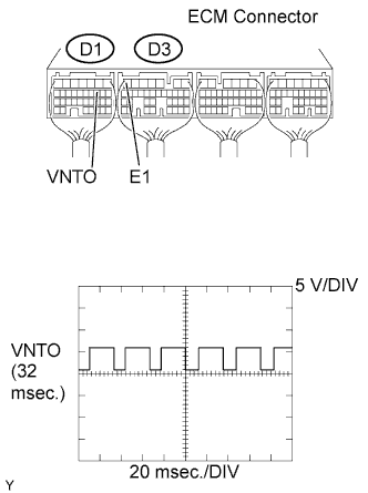
While idling the engine, check the waveform of the ECM connectors using an oscilloscope.
Standard voltage Tester Connection Specified Condition VNTO (D1-10) - E1 (D3-7) Correct waveform is as shown
NG
REPLACE ECM
OK
-
-
INSPECT ECM (VNTI VOLTAGE)
-
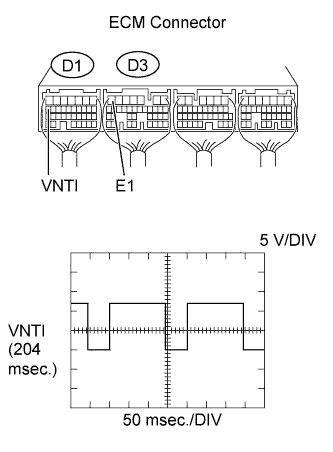
While idling the engine, check the waveform of the ECM connectors using an oscilloscope.
Standard voltage Tester Connection Specified Condition VNTI (D1-17) - E1 (D3-7) Correct waveform is as shown
NG
REPLACE TURBO MOTOR DRIVER
OK
-
-
INSPECT TURBOCHARGER SUB-ASSEMBLY (DC MOTOR OPERATION)
-
Turn the ignition switch to ON.
-
Turn the ignition switch to OFF and check the DC motor operation (check the operation link connected to the DC motor movement).
OK When the ignition switch is turned to OFF, the operation link moves as shown in A to D in the illustration below and the operation link contacts the stopper bolt 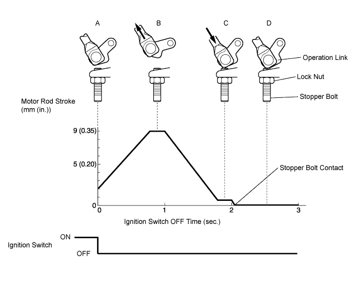
-
Connect an intelligent tester to the DLC3.
-
Start the engine and warm it up and turn the tester ON.
-
Select the following menu items: Powertrain / Engine / Data List.
-
Select the following menu items and read the value.
-
MAP
-
MAF
Standard value Item Engine Speed* Specified Condition MAP 3,000 rpm (full throttle acceleration) Min.: 185 kPa (1,387 mmHg, 54.6 in.Hg) MAF 3,000 rpm (full throttle acceleration) Min.: 120 g/sec. Tech Tips
*: The A/C switch and all accessory switches should be OFF, and the engine should be fully warmed up.
OK Values are within standard range and malfunction does not recur. Result Operation Link Condition Tester Display Proceed To Operation link moves correctly Outside standard range
(malfunction recurs)
A Within standard range C Operation link moves not correctly Outside standard range
(malfunction recurs)
B -
B
INSPECT TURBOCHARGER SUB-ASSEMBLY (DC MOTOR) Click here
C
CHECK FOR INTERMITTENT PROBLEMS
A
-
-
INSPECT FRONT EXHAUST PIPE ASSEMBLY
-
Visually confirm whether the front exhaust pipe is blocked. If blocked, replace the pipe.
Tech Tips
Blockage may not be found with a visual inspection alone.
OK No blockage
NG
REPAIR OR REPLACE FRONT EXHAUST PIPE ASSEMBLY
OK
-
-
CONFIRM WHETHER MALFUNCTION HAS BEEN SUCCESSFULLY REPAIRED
-
Connect an intelligent tester to the DLC3.
-
Start the engine and warm it up and turn the tester ON.
-
Select the following menu items: Powertrain / Engine / Data List.
-
Select the following menu items and read the value.
-
MAP
-
MAF
Standard value Item Engine Speed* Specified Condition MAP 3,000 rpm (full throttle acceleration) Min.: 185 kPa (1,387 mmHg, 54.6 in.Hg) MAF 3,000 rpm (full throttle acceleration) Min.: 120 g/sec. Tech Tips
*: The A/C switch and all accessory switches should be OFF, and the engine should be fully warmed up.
OK Values are within standard value and malfunction has been successfully repaired. -
NG
INSPECT MANIFOLD ABSOLUTE PRESSURE SENSOR Click here
OK
END
-
-
CHECK AND REPLACE FUEL FILTER ASSEMBLY
NEXT
-
CONFIRM WHETHER MALFUNCTION HAS BEEN SUCCESSFULLY REPAIRED
-
Connect an intelligent tester to the DLC3.
-
Start the engine and warm it up, and turn the tester ON.
-
Select the following menu items: Powertrain / Engine / Data List.
-
Select the following menu item and read the values.
-
Fuel Press
Standard value Item Engine Speed * Specified Condition Fuel Press Idling 30 to 40 MPa 2,000 rpm (No engine load) 50 to 60 MPa 3,000 rpm (No engine load) 85 to 105 MPa 3,000 rpm (full throttle acceleration) Min.: 170 MPa Tech Tips
*: The A/C switch and all accessory switches should be OFF, and the engine should be fully warmed up.
OK The values are within the standard range. -
OK
END
NG
-
-
INSPECT SUPPLY PUMP ASSEMBLY
-
Inspect the supply pump assembly, referring to the inspection procedure for DTC P0093 and P0627 Click here Click here.
NG
REPLACE SUCTION CONTROL VALVE
OK
-
-
INSPECT COMMON RAIL ASSEMBLY (FUEL PRESSURE SENSOR)
-
Inspect the common rail assembly (fuel pressure sensor), referring to the inspection procedure for DTC P0087 Click here.
NG
REPLACE COMMON RAIL ASSEMBLY
OK
-
-
INSPECT COMMON RAIL ASSEMBLY (PRESSURE DISCHARGE VALVE)
-
Inspect the common rail assembly (pressure discharge valve), referring to the inspection procedure for DTC P1271 Click here.
NG
REPLACE COMMON RAIL ASSEMBLY
OK
REPAIR OR REPLACE FUEL SYSTEM (FUEL LINE, AIR BLEED PROBLEM)
-
-
INSPECT MANIFOLD ABSOLUTE PRESSURE SENSOR
-
Check the vacuum hoses connected to the manifold absolute pressure sensor.
-
Check that the vacuum hoses connected to the manifold absolute pressure sensor and the gas filter are not clogged.
OK Vacuum hoses and gas filter are not clogged -
Check the vacuum hose connection.
OK Vacuum hoses are securely connected to sensor
-
-
Inspect the manifold absolute pressure sensor output.
-
Turn the ignition switch to ON.
-
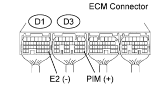
Measure the voltage of the ECM connectors.
Standard voltage Tester Connection Condition Specified Condition PIM (D3-28) - E2 (D1-28) Applied negative pressure of 40 kPa (300 mmHg, 11.8 in.Hg) 0.1 to 0.7 V PIM (D3-28) - E2 (D1-28) Same as atmospheric pressure 0.8 to 1.5 V PIM (D3-28) - E2 (D1-28) Applied positive pressure of 170 kPa (1,275 mmHg, 50.2 in.Hg) 1.6 to 2.3 V Tech Tips
Even when the output voltage from the manifold absolute pressure sensor is within the specified voltage range, there may be a problem in the sensor caused by age deterioration.
-
NG
REPLACE MANIFOLD ABSOLUTE PRESSURE SENSOR
OK
-
-
INSPECT MASS AIR FLOW METER
-
Read values using an intelligent tester (MAF).
Note
-
Turn the ignition switch to OFF.
-
Perform the inspection with the vehicle indoors and on a level surface.
-
Perform the inspection of the mass air flow meter while it is installed in the air cleaner case (installed on the vehicle).
-
During the test, do not use the exhaust air duct to perform suction on the exhaust pipe.
-
Turn the ignition switch ON (do not run the engine).
-
Turn the tester ON.
-
Select the following menu items: Powertrain / Engine / Data List / MAF.
-
Wait 30 seconds, and read the values on the intelligent tester.
Standard condition Less than 0.50 g/sec
-
-
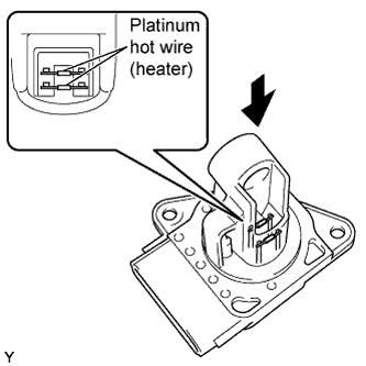
Using a work light, check that the platinum filament (heater portion) in the mass air flow meter has no foreign matter attached.
Standard No foreign matter attached.
NG
REPLACE MASS AIR FLOW METER
OK
END
-
-
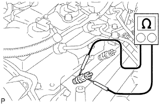
INSPECT TURBOCHARGER SUB-ASSEMBLY (DC MOTOR)
-
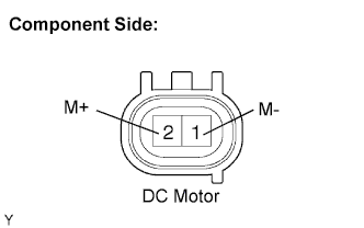
Disconnect the D65 DC motor connector.
-
Measure the DC motor resistance.
Standard resistance 1 to 100 Ω
NG
REPLACE TURBOCHARGER SUB-ASSEMBLY
OK
-
-
CHECK HARNESS AND CONNECTOR (DC MOTOR - TURBO MOTOR DRIVER)
-
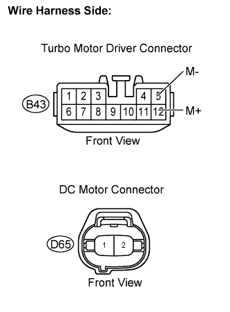
Disconnect the D65 DC motor connector.
-
Disconnect the B43 turbo motor driver connector.
-
Measure the resistance of the wire harness side connector.
Standard resistance (Check for open) Tester Connection Specified Condition M+ (B43-12) - D65-2 Below 1 Ω M- (B43-5) - D65-1 Below 1 Ω Standard resistance (Check for short) Tester Connection Specified Condition M+ (B43-12) or D65-2 - Body ground 10 kΩ or higher M- (B43-5) or D65-1 - Body ground 10 kΩ or higher -
Reconnect the turbo motor driver connector.
-
Reconnect the DC motor connector.
NG
REPAIR OR REPLACE HARNESS OR CONNECTOR
OK
-
-
REPLACE TURBO MOTOR DRIVER
NEXT
-
CONFIRM WHETHER MALFUNCTION HAS BEEN SUCCESSFULLY REPAIRED
-
Connect an intelligent tester to the DLC3.
-
Start the engine and warm it up, and turn the tester ON.
-
Select the following menu items: Powertrain / Engine / Data List.
-
Select the following menu item and read the values.
-
Fuel Press
Standard value Item Engine Speed * Specified Condition Fuel Press Idling 30 to 40 MPa 2,000 rpm (no engine load) 50 to 60 MPa 3,000 rpm (no engine load) 85 to 105 MPa 3,000 rpm (full throttle acceleration) Min.: 170 MPa Tech Tips
*: The A/C switch and all accessory switches should be OFF, and the engine should be fully warmed up.
OK The values are within the standard range and malfunction does not recur. -
B
END
A
REPLACE TURBOCHARGER SUB-ASSEMBLY
-