ECD SYSTEM (w/o DPF), Diagnostic DTC:P2BAB

| DTC Code | DTC Name |
|---|---|
| P2BAB | NOx Exceedance - Incorrect EGR Flow |
DESCRIPTION
The EGR system recirculates exhaust gases, in order to suit every driving condition. The recirculated gas mingles with intake air, therefore the EGR system can slow combustion speed and keep the combustion temperature down. This helps reduce NOx emission.
In order to increase EGR circulation efficiency, the ECM adjusts the lift amount of the electric EGR control valve and throttle valve angle.
| DTC No. | DTC Detection Condition | Trouble Area |
|---|---|---|
| P2BAB | After engine is warmed up, mass air flow rate is not changed when decelerating by releasing the accelerator pedal. (2 trip detection logic) |
|
MONITOR DESCRIPTION
If the electric EGR control valve is forcibly operated but the intake air amount does not vary, the ECM determines that the electric EGR control valve is malfunctioning. The ECM then illuminates the MIL.
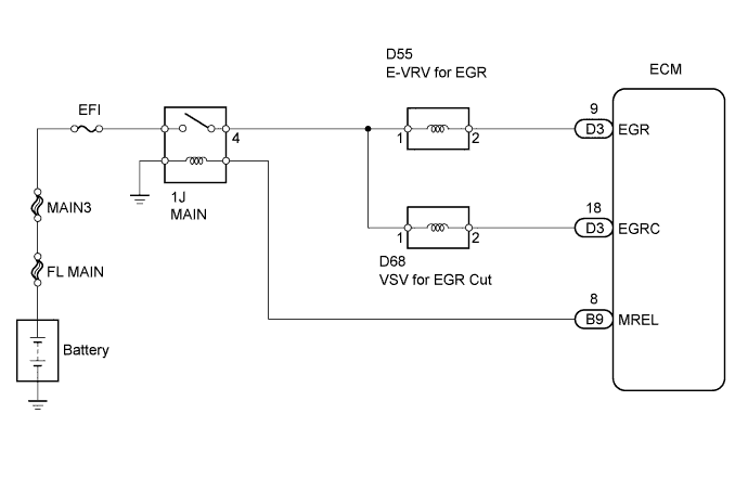
WIRING DIAGRAM
INSPECTION PROCEDURE
Note
After replacing the ECM, the new ECM needs registration Click here and initialization Click here.
Tech Tips
-
When this DTC is stored the vehicle enters fail-safe mode, in which the MIL blinks and the ECM measures elapsed time until an idle signal has been input or engine speed is below 200 rpm after 50 hours, after which engine output is limited to 75%.
-
Read freeze frame data using an intelligent tester. Freeze frame data record the engine condition when malfunctions are detected. When troubleshooting, freeze frame data can help determine if the vehicle was moving or stationary, if the engine was warmed up or not, if the air-fuel ratio was lean or rich, and other data, from the time the malfunction occurred.
PROCEDURE
-
CHECK ANY OTHER DTCS OUTPUT (IN ADDITION TO DTC P2BAB)
-
Connect an intelligent tester to the DLC3.
-
Turn the ignition switch to ON and turn the tester ON.
-
Select the following menu items: Powertrain / Engine / DTC.
-
Read DTCs.
Result Display (DTC Output) Proceed To P2BAB A P2BAB and other DTCs B Tech Tips
If any DTCs other than P2BAB are output, troubleshoot those DTCs first.
B 
GO TO DTC CHART
A 
-
-
CHECK FOR EXHAUST GAS LEAKS
-
Check for exhaust gas leaks.
Result Result Proceed To Exhaust gas leaks out from exhaust system A No leaks B
B 
CHECK AIR INTAKE SYSTEM (AIR LEAKS AND BLOCKAGES) Click here
A
-
-
REPAIR EXHAUST GAS LEAK POINT
-
Repair or replace the malfunctioning part in exhaust system.
NEXT
-
-
CHECK AIR INTAKE SYSTEM (AIR LEAKS AND BLOCKAGES)
-
Check for air leaks and blockages in the air intake system.
Result Result Proceed To Leaks or blockages exist in the air intake system A No leaks and blockages in the air intake system B Tech Tips
-
Check for abnormal disconnection, pipe and hose squashing, and any damages in the air intake system.
-
Using your hand, check whether the pipes and hoses in the air intake system are securely connected.
-
Applying soapy water and revving the engine, air leaks from the air intake system can be checked.
-
Check for any modifications in the air intake system made by the user.
-
B
INSPECT ELECTRIC EGR CONTROL VALVE ASSEMBLY (EGR VALVE OPERATION) Click here
A
-
-
REPAIR OR REPLACE AIR INTAKE SYSTEM
-
Repair or replace the malfunctioning part in the air intake system.
NEXT
-
-
INSPECT ELECTRIC EGR CONTROL VALVE ASSEMBLY (EGR VALVE OPERATION)
-
Inspect the electric EGR control valve assembly Click here.
OK The valve is not stuck and does not have heavy carbon deposits. Result Result Proceed To NG A OK B
B
CHECK FOR BLOCKAGE IN EGR GAS PASSAGE (EXHAUST MANIFOLD - EGR COOLER - ELECTRIC EGR CONTROL VALVE) Click here
A
-
-
REPLACE ELECTRIC EGR CONTROL VALVE ASSEMBLY
-
Replace the electric EGR control valve assembly.
NEXT
-
-
CHECK FOR BLOCKAGE IN EGR GAS PASSAGE (EXHAUST MANIFOLD - EGR COOLER - ELECTRIC EGR CONTROL VALVE)
-
Check for blockage in the EGR gas passage from the exhaust manifold, through the EGR cooler assembly to the electric EGR control valve assembly.
OK No blockage in the EGR gas passage. Result Result Proceed To NG A OK B
B
CHECK WHETHER DTC OUTPUT RECURS Click here
A
-
-
REPAIR OR REPLACE MALFUNCTIONING PARTS, COMPONENT AND AREA
-
Repair or replace the malfunctioning parts, component and area.
NEXT
-
-
CHECK WHETHER DTC OUTPUT RECURS
-
Connect the intelligent tester to the DLC3.
-
Turn the ignition switch to ON and turn the tester on.
-
Start the engine and warm it up until the engine coolant temperature reaches 80°C (176°F).
-
Drive the vehicle at 50 km/h (31 mph) or more and then fully release the accelerator pedal for 5 seconds or more.
-
Select the following menu items: Powertrain / Engine / DTC.
-
Read the DTC.
Result Display (DTC Output) Proceed To P2BAB A No output B
B
END
A
-
-
REPLACE EGR COOLER ASSEMBLY
-
Replace the EGR cooler assembly.
NEXT
-
-
CONFIRM WHETHER MALFUNCTION HAS BEEN SUCCESSFULLY REPAIRED
-
Connect the intelligent tester to the DLC3.
-
Turn the ignition switch to ON and turn the tester on.
-
Start the engine and warm it up until the engine coolant temperature reaches 80°C (176°F).
-
Drive the vehicle at 50 km/h (31 mph) or more and then fully release the accelerator pedal for 5 seconds or more.
-
Select the following menu items: Powertrain / Engine / DTC.
-
Confirm that the DTC is not output again.
Tech Tips
If the DTC is output again, the mass air flow meter may be malfunctioning.
NEXT 
END
-