ECD SYSTEM (w/o DPF), Diagnostic DTC:P1264

| DTC Code | DTC Name |
|---|---|
| P1264 | VN Turbo Controller Malfunction |
DESCRIPTION
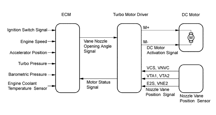
The turbocharger system is comprised of the Variable Nozzle (VN) type turbocharger, the turbo motor driver and ECM.
The turbocharger has a nozzle vane which opens and closes to control the volume of the exhaust gas flowing into the turbine. This, in turn, controls the boost pressure, when the nozzle vane moves towards the closing direction, the pressure increases. When the vane moves towards the opening direction, the pressure decreases.
The turbocharger actuator, which consists of the DC motor and the nozzle vane position sensor, is built on the turbocharger sub-assembly, and activates the nozzle vane. The nozzle vane position sensor detects the opening angle of the nozzle vane. The turbo motor driver receives an opening angle request from the ECM and a nozzle vane position signal from the nozzle vane position sensor. Based on these signals, the turbo motor driver operates the DC motor and adjusts the nozzle vane opening angle. The turbo motor driver sends the status as a turbo driver status signal to the ECM
The ECM sends a target nozzle vane position signal to the turbo motor driver to obtain the nozzle vane position for the optimal boost pressure in accordance with the driving conditions.
| DTC No. | DTC Detection Condition | Trouble Area |
|---|---|---|
| P1264 | When communication error occurs between turbo motor and ECM (1 trip detection logic) |
|
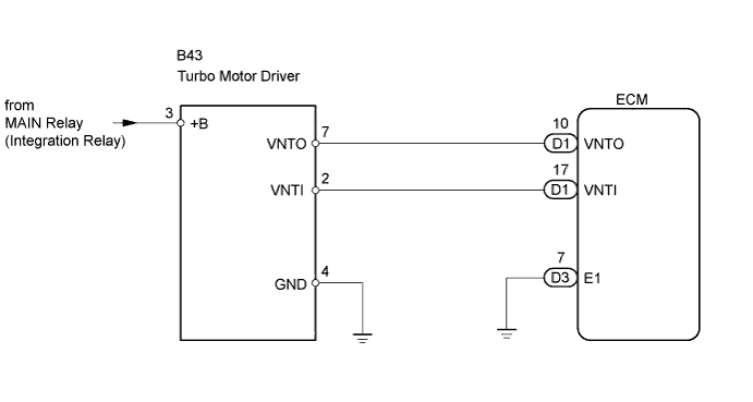
WIRING DIAGRAM
INSPECTION PROCEDURE
Tech Tips
-
Read freeze frame data using an intelligent tester. Freeze frame data record the engine condition when malfunctions are detected. When troubleshooting, freeze frame data can help determine if the vehicle was moving or stationary, if the engine was warmed up or not, if the air-fuel ratio was lean or rich, and other data, from the time the malfunction occurred.
-
Excessive electrical noise, such as from wireless radios or electrical modifications, may cause a DTC output.
Note
After replacing the ECM, the new ECM needs registration Click here and initialization Click here.
PROCEDURE
-
INSPECT TURBO MOTOR DRIVER
-
Disconnect the B43 turbo motor driver connector.
-
Turn the ignition switch to ON.
-
Measure the voltage of the turbo motor driver connector.
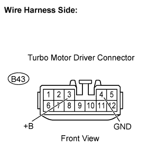
Standard voltage Tester Connection Specified Condition +B (B43-3) - GND (B43-4) 11 to 14 V -
Check the resistance.
Standard resistance Tester Connection Specified Condition GND (B43-4) - Body ground Below 1 Ω -
Reconnect the turbo motor driver connector.
NG 
REPAIR OR REPLACE HARNESS OR CONNECTOR
OK 
-
-
CHECK HARNESS AND CONNECTOR (TURBO MOTOR DRIVER - ECM)
-
Disconnect the D1 ECM connector.
-
Disconnect the B43 turbo motor driver connector.
-
Check the resistance.
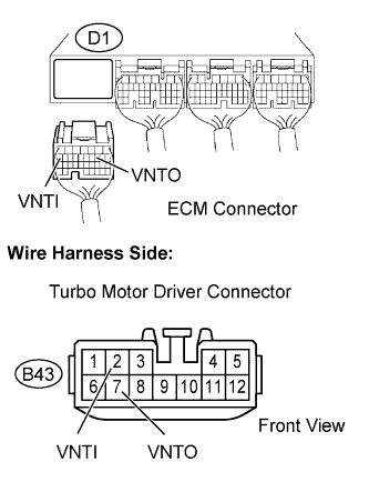
Standard resistance (Check for open) Tester Connections Specified Conditions VNTO (D1-10) - VNTO (B43-7) Below 1 Ω VNTI (D1-17) - VNTI (B43-2) Below 1 Ω Standard resistance (Check for short) Tester Connections Specified Conditions VNTO (D1-10) or VNTO (B43-7) - Body ground 10 kΩ or higher VNTI (D1-17) or VNTI (B43-2) - Body ground 10 kΩ or higher -
Reconnect the turbo motor driver connector.
-
Reconnect the ECM connector.
NG
REPAIR OR REPLACE HARNESS OR CONNECTOR
OK
-
-
INSPECT ECM (VNTO VOLTAGE)
-
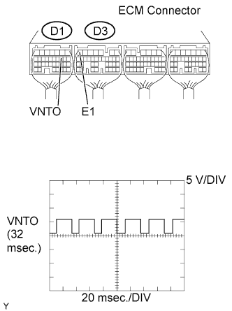
While idling the engine, check the waveform of the ECM connectors using an oscilloscope.
Standard voltage Tester Connection Specified Condition VNTO (D1-10) - E1 (D3-7) Correct waveform is as shown
NG
REPLACE ECM
OK
-
-
INSPECT ECM (VNTI VOLTAGE)
-
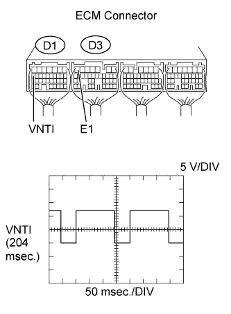
While idling the engine, check the waveform of the ECM connectors using an oscilloscope.
Standard voltage Tester Connection Specified Condition VNTI (D1-17) - E1 (D3-7) Correct waveform is as shown
NG
REPLACE TURBO MOTOR DRIVER
OK 
CHECK FOR INTERMITTENT PROBLEMS
-