ECD SYSTEM (w/o DPF), Diagnostic DTC:P1251

| DTC Code | DTC Name |
|---|---|
| P1251 | Turbocharger / Supercharger Overboost Condition (Too High) |
DESCRIPTION
| DTC Detection Drive Pattern | DTC Detection Condition | Trouble Area |
|---|---|---|
| Vehicle being driven | Boost pressure is higher than the threshold* for 5 seconds. (1 trip detection logic). |
|
Tech Tips
*: The threshold value changes depending on the engine speed.
| DTC No. | Data List |
|---|---|
| P1251 |
|
Tech Tips
If DTC P1251 is stored due to the VN turbo vane being stuck closed, the following symptoms may appear:
-
Vehicle surge when driving with full load
-
Sudden lack of power due to power being limited
INSPECTION PROCEDURE
Tech Tips
Read freeze frame data using the intelligent tester. Freeze frame data records the engine condition when malfunctions are detected. When troubleshooting, freeze frame data can help determine if the vehicle was moving or stationary, if the engine was warmed up or not, and other data from the time the malfunction occurred.
Note
After replacing the ECM, the new ECM needs registration Click here and initialization Click here.
PROCEDURE
-
CHECK FOR ANY OTHER DTCS OUTPUT (RECORD STORED DTC AND FREEZE FRAME DATA)
-
Connect the intelligent tester to the DLC3.
-
Turn the ignition switch ON and turn the tester on.
-
Enter the following menus: Powertrain / Engine and ECT / DTC.
-
Read the DTCs.
Tech Tips
Record the stored DTC and Freeze Frame Data.
Result Result Proceed to P1251 A P1251 and other DTCs B Tech Tips
DC motor-related DTCs: P0046 Click here.
DC motor-related DTCs: P0047 and P0048 Click here.
Nozzle vane position sensor-related DTCs: P2563, P2564, P2565, P2588 and P2589 Click here.
B 
GO TO DTC CHART Click here
A 
-
-
CHECK AIR INTAKE SYSTEM
-
Check if the hoses between the air cleaner and turbocharger, and turbocharger and intake manifold are damaged or disconnected.
Result Result Proceed to Hoses or pipes are damaged or disconnected A No hoses or pipes are damaged or disconnected B Tech Tips
-
Be sure to check if the hoses and pipes between the air cleaner and compressor are disconnected as disconnection of a hose or pipe can cause overboost. Also, check the high pressure hoses for disconnection due to overboost.
-
Check for disconnection of the exhaust pipes.
-
Using your hand, check whether the pipes and hoses in the intake system are securely connected.
-
Check for any modifications in the intake system made by the user.
-
B 
CHECK TURBOCHARGER SUB-ASSEMBLY (DC MOTOR OPERATION) Click here
A
-
-
REPAIR OR REPLACE AIR INTAKE SYSTEM
-
Repair or replace the malfunctioning part in the air intake system.
NEXT
-
-
CHECK TURBOCHARGER SUB-ASSEMBLY (DC MOTOR OPERATION)
-
Check the turbocharger sub-assembly Click here.
Tech Tips
Check the movement of the actuator rod when the ignition switch is turned from ON to OFF.
NG
CHECK HARNESS AND CONNECTOR (DC MOTOR, NOZZLE VANE POSITION SENSOR - TURBO MOTOR DRIVER) Click here
OK
-
-
PERFORM ACTIVE TEST USING INTELLIGENT TESTER (CONTROL THE EGR SYSTEM)
-
Connect the intelligent tester to the DLC3.
-
Start the engine and warm it up, and make sure the A/C switch and all accessory switches are off.
-
Turn the ignition switch OFF. Wait for 30 seconds, and then restart the engine.
-
Turn the tester on.
-
Enter the following menus: Powertrain / Engine and ECT / Data List / MAF.
-
Read the MAF value displayed on the tester while the engine is idling.
-
Enter the following menus: Powertrain / Engine and ECT / Active Test / Control the EGR System.
-
Read the mass air flow meter value when the VSV for EGR Cut or electric vacuum regulating valve assembly is turned from off to on using the Active Test function.
Tech Tips
-
If idling continues for 15 minutes or more, the "EGR position" becomes 0% (EGR valve fully closed). As this makes diagnosis impossible, it becomes necessary to drive the vehicle or to restart the engine.
-
Before performing the diagnosis, confirm that the "EGR position" is not 0%.
-
If MAF does not change when the EGR is cut even though the EGR valve is operating normally, the EGR cooler may be clogged.
Result Active Test Result Proceed to Control the EGR System:
Off (Open) to on (Close)
MAF value does not change A MAF value changes B Note
As the values shown below may differ due to factors such as differences in measuring environments and changes in vehicle condition due to aging, do not use these values to determine whether the vehicle is malfunctioning or not.
Tech Tips
The problem may be a temporary one, due to the entry of deposits or foreign matter. Check that there are no deposits or foreign matter in the electric vacuum regulating valve assembly or mass air flow meter.
Reference EGR Valve Condition (Opening) Measuring Condition MAF (Reference) Open (55%)
-
Atmosphere pressure: 101 kPa
-
Intake air temperature: 30°C (86°F)
-
Engine coolant temperature: 88°C (190°F)
4.5 to 10.5 g/sec Close (0%) 13 to 20 g/sec -
B
READ VALUE USING INTELLIGENT TESTER (INJECTION VOLUME) Click here
A
-
-
READ VALUE USING INTELLIGENT TESTER (EGR LIFT POSITION)
-
Check the change in the values of "EGR Lift Position" in the Data List from the time when the "Control the EGR System" Active Test was performed in the previous step.
Result Result Proceed to Value of "EGR Lift Position" remains close to or at value that indicates valve is fully close A Except above B Tech Tips
The value of "EGR Lift Position" that indicates that the valve is fully closed can be determined by using the formula below and comparing the result to the value of "EGR Close Learning Value". If the calculated value is close to the value of "EGR Close Learning Value" and does not change, it can be determined that the valve is stuck closed.
Example: When "EGR Lift Position" is 15%, use the following formula: 0.15 x 5 = 0.75 V Then compare the result (0.75 V) to the value of "EGR Close Learning Value".
B
REPLACE EGR COOLER Click here
A
-
-
CHECK ELECTRIC EGR CONTROL VALVE ASSEMBLY (CHECK VACUUM)
-
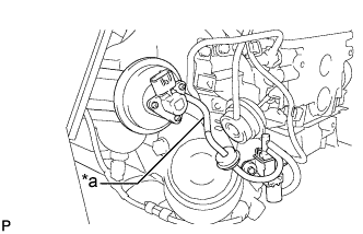
Text in Illustration *a Vacuum hose Disconnect the vacuum hose from the electric EGR control valve assembly.
-
Start the engine.
-
Check if there is suction from the vacuum hose during idling.
Tech Tips
If idling continues for 15 minutes or more, the "EGR position" becomes 0% (EGR valve fully closed). As this makes diagnosis impossible, it becomes necessary to drive the vehicle or to restart the engine.
OK Suction exists.
NG
REPAIR OR REPLACE VACUUM HOSE Click here
OK
-
-
REMOVE DEPOSIT (ELECTRIC EGR CONTROL VALVE ASSEMBLY)
-
Remove the electric EGR control valve assembly Click here.
-
Visually check the electric EGR control valve assembly for deposits. If there are deposits, clean the electric EGR control valve assembly.
Tech Tips
-
If the EGR valve is stuck closed, the intake air amount increases and engine vibration may worsen.
-
If the EGR valve does not operate due to clogging or disconnection of the vacuum hose, repair the hose.
-
If the EGR valve does not close properly or is stuck open, EGR becomes excessive and combustion becomes unstable. Also, there may be a lack of power.
-
-
Reinstall the electric EGR control valve assembly Click here.
NEXT
CONFIRM WHETHER MALFUNCTION HAS BEEN SUCCESSFULLY REPAIRED Click here
-
-
REPAIR OR REPLACE VACUUM HOSE
-
Repair or replace of the EGR valve system vacuum hose.
NEXT
CONFIRM WHETHER MALFUNCTION HAS BEEN SUCCESSFULLY REPAIRED Click here
-
-
REPLACE EGR COOLER
-
Replace the EGR cooler.
NEXT
CONFIRM WHETHER MALFUNCTION HAS BEEN SUCCESSFULLY REPAIRED Click here
-
-
READ VALUE USING INTELLIGENT TESTER (INJECTION VOLUME)
-
Connect the intelligent tester to the DLC3.
-
Start the engine and warm it up until the engine coolant temperature reaches 70°C (158°F) or higher.
-
Allow the engine to idle for 1 minute or more.
Tech Tips
The A/C switch and all accessory switches should be off with a fully warm engine.
-
Turn the tester on.
-
Enter the following menus: Powertrain / Engine and ECT / Data List / Injection Volume.
-
Read the values during engine idling.
Result Result Proceed to Injection Volume is less than 5 mm3/st
A Except above B Tech Tips
-
If the injector assembly is malfunctioning, the compensatory injection volume remains at 5.0 mm3/st.
-
If there is a disconnection, the feedback value will increase and +5.0 mm3/st will be indicated, because it will become impossible for the injector to inject.
-
B
CONFIRM WHETHER MALFUNCTION HAS BEEN SUCCESSFULLY REPAIRED Click here
A
-
-
REPLACE INJECTOR ASSEMBLIES OF ALL CYLINDERS
-
Replace the injector assemblies Click here.
NEXT
-
-
BLEED AIR FROM FUEL SYSTEM
-
Using the hand pump mounted on the fuel filter cap, bleed the air from the fuel system. Continue pumping until the pump resistance increases.
Note
-
The maximum hand pump pumping speed is 2 strokes per second.
-
The hand pump must be pushed with a full stroke during pumping.
-
When the fuel pressure at the supply pump inlet port reaches a saturated pressure, the hand pump resistance increases.
-
If pumping is interrupted during the air bleeding process, fuel in the fuel line may return to the fuel tank. Continue pumping until the hand pump resistance increases.
-
If the hand pump resistance does not increase despite consecutively pumping 200 times or more, there may be a fuel leak between the fuel tank and fuel filter, the hand pump may be malfunctioning, or the vehicle may have run out of fuel.
-
If air bleeding using the hand pump is incomplete, the common rail pressure does not rise to the pressure range necessary for normal use and the engine cannot be started.
-
-
Start the engine.
Note
-
Even if air bleeding using the hand pump has been completed, the starter may need to be cranked for 10 seconds or more to start the engine.
-
Do not crank the engine continuously for more than 20 seconds. The battery may be discharged.
-
Use a fully-charged battery.
-
When the engine can be started, proceed to the next step.
-
If the engine cannot be started, bleed the air again using the hand pump until the hand pump resistance increases (refer to the procedures above). Then start the engine.
-
-
Turn the ignition switch OFF.
-
Connect the intelligent tester to the DLC3.
-
Turn the ignition switch ON and turn the tester ON.
-
Clear the DTCs Click here.
-
Start the engine.*1
-
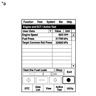
Text in Illustration *a Reference
Active Test Operation
Enter the following menus: Powertrain / Engine and ECT / Active Test / Test the Fuel Leak.*2
-
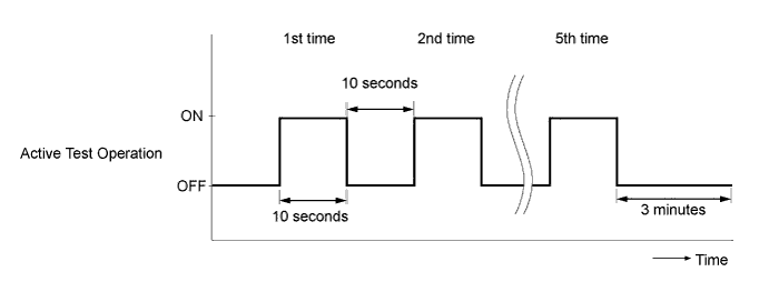
Perform the following test 5 times with on/off intervals of 10 seconds: Active Test / Test the Fuel Leak.*3
-
Allow the engine to idle for 3 minutes or more after performing the Active Test for the 5th time.
Tech Tips
When the Active Test "Test the Fuel Leak" is used to change the pump control mode, the actual fuel pressure inside the common rail drops below the target fuel pressure when the Active Test is off, but this is normal and does not indicate a pump malfunction.
-
Enter the following menus: Powertrain / Engine and ECT / DTC.
-
Read Current DTCs.
-
Clear the DTCs Click here.
-
Repeat steps *1 to *3.
-
Enter the following menus: Powertrain / Engine and ECT / DTC.
-
Read Current DTCs.
OK No DTCs are output.
NEXT
-
-
REGISTER INJECTOR COMPENSATION CODE
-
Register the injector compensation code Click here.
NEXT
-
-
CONFIRM WHETHER MALFUNCTION HAS BEEN SUCCESSFULLY REPAIRED
-
Connect the intelligent tester to the DLC3.
-
Clear the DTCs Click here.
-
Turn the ignition switch OFF.
-
Start the engine and warm it up.
-
Confirm the value of Engine Speed from the Freeze Frame Data recorded previously, and then drive the vehicle according to the Engine Speed value.
-
Read the DTCs.
Result Result Proceed to P1251 is not output and MAP is 220 kPa or less A Except above B* Tech Tips
*: Return to "Check Air Intake System" and inspect areas that have not been inspected yet.
B
CHECK AIR INTAKE SYSTEM Click here
A 
END
-
-
CHECK HARNESS AND CONNECTOR (DC MOTOR, NOZZLE VANE POSITION SENSOR - TURBO MOTOR DRIVER)
-
Disconnect the D65 DC motor connector.
-
Disconnect the D66 nozzle vane position sensor connector.
-
Disconnect the B43 turbo motor driver connector.
-
Check the resistance.
Standard resistance (Check for open) Tester Connections Specified Conditions M+ (B43-12) - D65-2 Below 1 Ω M- (B43-5) - D65-1 Below 1 Ω VTA1 (D66-1) - VTA1 (B43-9) Below 1 Ω VNE2 (D66-2) - VNE2 (B43-8) Below 1 Ω VNVC (D66-3) - VNVC (B43-1) Below 1 Ω VTA2 (D66-4) - VTA2 (B43-10) Below 1 Ω E2S (D66-5) - E2S (B43-11) Below 1 Ω VCS (D66-6) - VCS (B43-6) Below 1 Ω Standard resistance (Check for short) Tester Connections Specified Conditions M+ (B43-12) or D65-2 - Body ground 10 kΩ or higher M- (B43-5) or D65-1 - Body ground 10 kΩ or higher VTA1 (D66-1) or VTA1 (B43-9) - Body ground 10 kΩ or higher VNE2 (D66-2) or VNE2 (B43-8) - Body ground 10 kΩ or higher VNVC (D66-3) or VNVC (B43-1) - Body ground 10 kΩ or higher VTA2 (D66-4) or VTA2 (B43-10) - Body ground 10 kΩ or higher E2S (D66-5) or E2S (B43-11) - Body ground 10 kΩ or higher VCS (D66-6) or VCS (B43-6) - Body ground 10 kΩ or higher -
Reconnect the turbo motor driver connector.
-
Reconnect the nozzle vane position sensor connector.
-
Reconnect the DC motor connector.
NG
REPAIR OR REPLACE HARNESS OR CONNECTOR
OK
INSPECT TURBOCHARGER SUB-ASSEMBLY Click here
-