ECD SYSTEM (w/o DPF), Diagnostic DTC:P0617

| DTC Code | DTC Name |
|---|---|
| P0617 | Starter Relay Circuit High |
DESCRIPTION
While the engine is being cranked, the battery voltage is applied to terminal STA of the ECM. If the ECM detects the Starter Control (STA) signal while the vehicle is being driven, it determines that there is a malfunction in the STA circuit. The ECM then illuminates the MIL and sets the DTC.
This monitor runs when the vehicle is driven at 20 km/h (12.4 mph) for over 20 seconds.
| DTC No. | DTC Detection Conditions | Trouble Areas |
|---|---|---|
| P0617 | When conditions (a), (b) and (c) met, positive (+B) battery voltage 10.5 V or more applied to ECM for 20 seconds (1 trip detection logic)
|
|
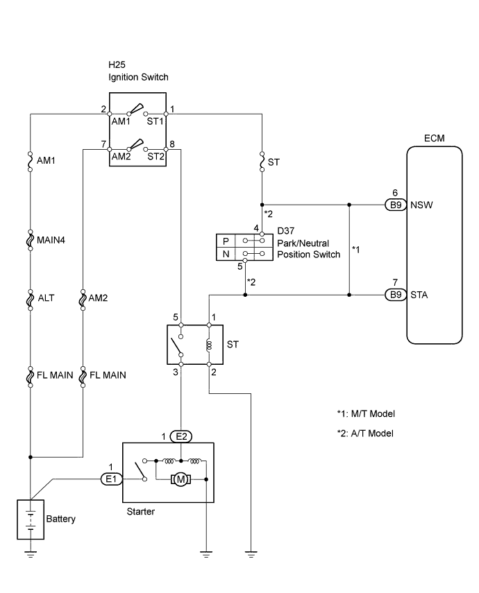
WIRING DIAGRAM
INSPECTION PROCEDURE
Note
After replacing the ECM, the new ECM needs registration Click here and initialization Click here.
Tech Tips
-
The following troubleshooting flowchart is based on the premise that the engine is cranked normally.
If the engine will not crank, proceed to the problem symptoms table Click here.
-
Read freeze frame data using an intelligent tester. Freeze frame data record the engine condition when malfunctions are detected. When troubleshooting, freeze frame data can help determine if the vehicle was moving or stationary, if the engine was warmed up or not, if the air-fuel ratio was lean or rich, and other data, from the time the malfunction occurred.
PROCEDURE
-
READ VALUE USING INTELLIGENT TESTER (STARTER SIGNAL)
-
Connect an intelligent tester to the DLC3.
-
Turn the ignition switch to ON and turn the tester ON.
-
Select the following menu items: Powertrain / Engine / Data List / Starter Signal.
-
Check the value displayed on the tester when the ignition switch is turned to the ON and START positions.
OK Ignition Switch Positions Starter Signal ON OFF START ON Result Result Proceed To OK A NG B (M/T Models) NG C (A/T Models)
A 
CHECK FOR INTERMITTENT PROBLEMS
B 
INSPECT IGNITION SWITCH Click here
C 
-
-
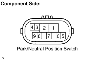
INSPECT PARK/NEUTRAL POSITION SWITCH ASSEMBLY
-
Disconnect the D37 park/neutral position switch connector.
-
Measure the resistance when the transmission gear selector lever is moved to each position.
Standard resistance Tester Connection Shift Lever Position Specified Condition 4 - 5 Except P and N 10 kΩ or higher 2 - 5 P 10 kΩ or higher R N D 2 L -
Reconnect the park/neutral position switch connector.
OK
INSPECT IGNITION SWITCH Click here
NG
-
-
REPLACE PARK/NEUTRAL POSITION SWITCH ASSEMBLY
NEXT
-
READ VALUE USING INTELLIGENT TESTER (STARTER SIGNAL)
-
Connect an intelligent tester to the DLC3.
-
Turn the ignition switch to ON and turn the tester ON.
-
Select the following menu items: Powertrain / Engine / Data List / Starter Signal.
-
Check the value displayed on the tester when the ignition switch is turned to the ON and START positions.
OK Ignition Switch Positions Starter Signal ON OFF START ON
OK
SYSTEM OK
NG
-
-
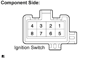
INSPECT IGNITION SWITCH
-
Disconnect the H25 ignition switch connector.
-
Measure the ignition switch resistance.
Standard resistance Tester Connection Ignition Switch Position Specified Condition All Terminals LOCK 10 kΩ or higher 1 - 2, 7 - 8 ON 2 - 3 ACC Below 1 Ω 2 - 3, 2 - 4, 6 - 7 ON 1 - 2, 2 - 4, 6 - 7, 7 - 8 START -
Reconnect the ignition switch connector.
OK
READ VALUE USING INTELLIGENT TESTER (STARTER SIGNAL) Click here
NG
-
-
REPLACE IGNITION SWITCH
NEXT
-
READ VALUE USING INTELLIGENT TESTER (STARTER SIGNAL)
-
Connect an intelligent tester to the DLC3.
-
Turn the ignition switch to ON and turn the tester ON.
-
Select the following menu items: Powertrain / Engine / Data List / Starter Signal.
-
Check the value displayed on the tester when the ignition switch is turned to the ON and START positions.
OK Ignition Switch Positions Starter Signal ON OFF START ON
OK
SYSTEM OK
NG
-
-
REPAIR OR REPLACE HARNESS OR CONNECTOR (IGNITION SWITCH - STA TERMINAL OF ECM)
NEXT
-
CHECK WHETHER DTC OUTPUT RECURS
-
Connect an intelligent tester to the DLC3.
-
Turn the ignition switch to ON and turn the tester ON.
-
Select the following menu items: Powertrain / Engine / DTC / Clear.
-
Clear DTCs.
-
Drive the vehicle at more than 20 km/h (12.43 mph) for 20 seconds or more.
-
Select the following menu items: Powertrain / Engine / DTC.
-
Read DTCs.
Result Display (DTC Output) Proceed To P0617 A No DTC B
B
SYSTEM OK
A 
REPLACE ECM
-