ECD SYSTEM (w/o DPF), Diagnostic DTC:P2121

| DTC Code | DTC Name |
|---|---|
| P2121 | Throttle / Pedal Position Sensor / Switch "D" Circuit Range / Performance |
DESCRIPTION
Refer to DTC P2120 Click here.
| DTC No. | DTC Detection Condition | Trouble Area |
|---|---|---|
| P2121 | Condition (a) continues for 2 seconds: (a) Difference between VPA1 and VPA2 exceeds the threshold (1 trip detection logic) |
|
WIRING DIAGRAM
Refer to DTC P2120 Click here.
INSPECTION PROCEDURE
Note
After replacing the ECM, the new ECM needs registration Click here and initialization Click here.
Tech Tips
Read freeze frame data using an intelligent tester. Freeze frame data record the engine condition when malfunctions are detected. When troubleshooting, freeze frame data can help determine if the vehicle was moving or stationary, if the engine was warmed up or not, if the air-fuel ratio was lean or rich, and other data, from the time the malfunction occurred.
PROCEDURE
-
READ VALUE USING INTELLIGENT TESTER (ACCELERATOR POSITION NO.1 AND ACCELERATOR POSITION NO.2)
-
Connect an intelligent tester to the DLC3.
-
Turn the ignition switch to ON and turn the tester ON.
-
Select the following menu items: Powertrain / Engine / Data List / Accel Position 1 and Accel Position 2.
-
Read the values.
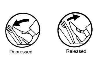
Standard voltage Accelerator Pedal Operation Accel Position 1 Accel Position 2 Released 0.5 to 1.1 V 0.9 to 2.3 V Depressed 3.0 to 4.6 V 3.4 to 5.0 V
OK 
REPLACE ECM
NG 
-
-
CHECK HARNESS AND CONNECTOR (ACCELERATOR PEDAL POSITION SENSOR - ECM)
-
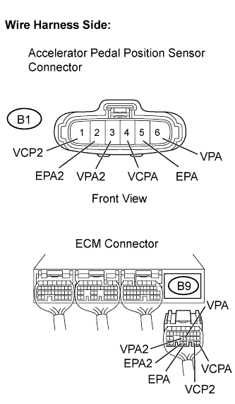
Disconnect the B1 accelerator pedal position sensor connector.
-
Disconnect the B9 ECM connector.
-
Check the resistance.
Standard resistance (Check for open) Tester Connection Specified Condition VCP2 (B1-1) - VCP2 (B9-27) Below 1 Ω EPA2 (B1-2) - EPA2 (B9-29) Below 1 Ω VPA2 (B1-3) - VPA2 (B9-23) Below 1 Ω VCPA (B1-4) - VCPA (B9-26) Below 1 Ω EPA (B1-5) - EPA (B9-28) Below 1 Ω VPA (B1-6) - VPA (B9-22) Below 1 Ω Standard resistance (Check for short) Tester Connection Specified Condition VCP2 (B1-1) or VCP2 (B9-27) - Body ground 10 kΩ or higher EPA2 (B1-2) or EPA2 (B9-29) - Body ground 10 kΩ or higher VPA2 (B1-3) or VPA2 (B9-23) - Body ground 10 kΩ or higher VCPA (B1-4) or VCPA (B9-26) - Body ground 10 kΩ or higher EPA (B1-5) or EPA (B9-28) - Body ground 10 kΩ or higher VPA (B1-6) or VPA (B9-22) - Body ground 10 kΩ or higher -
Reconnect the ECM connector.
-
Reconnect the accelerator pedal position sensor connector.
NG
REPAIR OR REPLACE HARNESS OR CONNECTOR
OK
-
-
REPLACE ACCELERATOR PEDAL ROD ASSEMBLY
-
Replace the accelerator pedal rod assembly Click here.
NEXT
-
-
CHECK WHETHER DTC OUTPUT RECURS (DTC P2121)
-
Connect an intelligent tester to the DLC3.
-
Turn the ignition switch to ON and turn the tester ON.
-
Select the following menu items: Powertrain / Engine / DTC / Clear.
-
Clear DTCs.
-
Start the engine.
-
Allow the engine to idle for 15 seconds.
-
Depress and release the accelerator pedal several times.
-
Select the following menu items: Powertrain / Engine / DTC.
-
Read DTCs.
Result Display (DTC Output) Proceed To P2121 A No output B
B
SYSTEM OK
A 
REPLACE ECM
-