ECD SYSTEM (w/o DPF), Diagnostic DTC:P0405, P0406

| DTC Code | DTC Name |
|---|---|
| P0405 | Exhaust Gas Recirculation Sensor "A" Circuit Low |
| P0406 | Exhaust Gas Recirculation Sensor "A" Circuit High |
DESCRIPTION
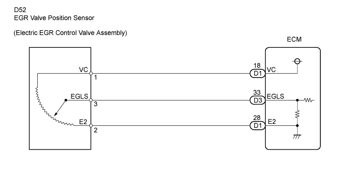
The EGR valve position sensor is mounted on the electric EGR control valve and used for detecting the lift amount of the valve. The lift amount detected by the sensor is provided to the ECM as feedback. The ECM then regulates the lift amount of the valve in accordance with engine running conditions.
| DTC No. | DTC Detection Condition | Trouble Area |
|---|---|---|
| P0405 | EGR valve position sensor output voltage less than 0.1 V for more than 5 seconds (1 trip detection logic) |
|
| P0406 | EGR valve position sensor output voltage more than 4.9 V for more than 5 seconds (1 trip detection logic) |
|
MONITOR DESCRIPTION
When output voltage of the EGR valve position sensor deviates from the normal operating range of 0.1 to 4.9 V for more than 5 seconds, the ECM interprets this as a malfunction of the sensor circuit, and illuminates the MIL.
WIRING DIAGRAM
INSPECTION PROCEDURE
Note
After replacing the ECM, the new ECM needs registration Click here and initialization Click here.
Tech Tips
-
When this DTC is stored the vehicle enters fail-safe mode, in which the MIL blinks and the ECM measures elapsed time until an idle signal has been input or engine speed is below 200 rpm after 50 hours, after which engine output is limited to 75%.
-
Read freeze frame data using an intelligent tester. Freeze frame data record the engine condition when malfunctions are detected. When troubleshooting, freeze frame data can help determine if the vehicle was moving or stationary, if the engine was warmed up or not, if the air-fuel ratio was lean or rich, and other data, from the time the malfunction occurred.
PROCEDURE
-
INSPECT ELECTRIC EGR CONTROL VALVE ASSEMBLY (EGR VALVE POSITION SENSOR POWER SOURCE)
-
Disconnect the D52 EGR valve position sensor connector.
-
Turn the ignition switch to ON.
-
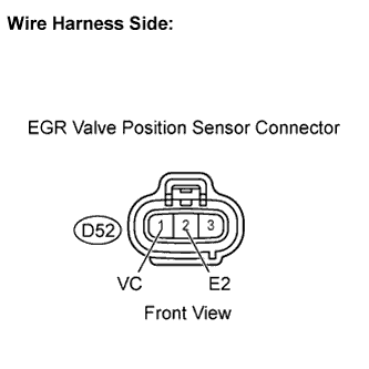
Measure the voltage of the wire harness side connector.
Standard voltage Tester Connection Specified Condition VC (D52-1) - E2 (D52-2) 4.5 to 5.5 V -
Reconnect the EGR valve position sensor connector.
NG 
CHECK HARNESS AND CONNECTOR (EGR VALVE POSITION SENSOR - ECM) Click here
OK 
-
-
INSPECT ELECTRIC EGR CONTROL VALVE ASSEMBLY (EGR VALVE POSITION SENSOR RESISTANCE)
-
Disconnect the EGR valve position sensor connector.
-
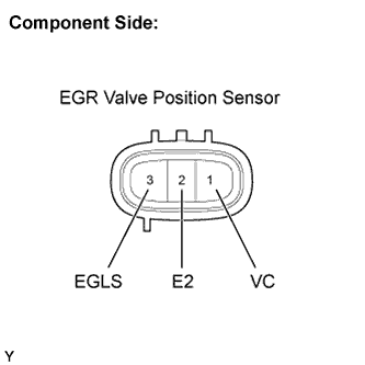
Measure the resistance of the EGR valve position sensor.
Standard resistance Tester Connection EGR Valve Condition Specified Condition VC (1)- E2 (2) - 3.5 to 6.5 kΩ
at 20°C (68°F)
EGLS (3) - E2 (2) Fully opened 3.9 kΩ
at 20°C (68°F)
EGLS (3) - E2 (2) Fully closed 1.0 kΩ
at 20°C (68°F)
-
Reconnect the EGR valve position sensor connector.
NG 
REPLACE ELECTRIC EGR CONTROL VALVE ASSEMBLY
OK
-
-
CHECK HARNESS AND CONNECTOR (EGR VALVE POSITION SENSOR - ECM)
-
Disconnect the D52 EGR valve position sensor connector.
-
Disconnect the D1 and D3 ECM connectors.
-
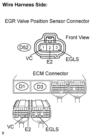
Check the resistance.
Standard resistance (Check for open) Tester Connection Specified Condition VC (D52-1) - VC (D1-18) Below 1 Ω EGLS (D52-3) - EGLS (D3-33) Below 1 Ω E2 (D52-2) - E2 (D1-28) Below 1 Ω Standard resistance (Check for short) Tester Connection Specified Condition EGLS (D52-3) or EGLS (D3-33) - Body ground 10 kΩ or higher VC (D52-1) or VC (D1-18) - Body ground 10 kΩ or higher -
Reconnect the ECM connectors.
-
Reconnect the EGR valve position sensor connector.
NG
REPAIR OR REPLACE HARNESS OR CONNECTOR
OK 
REPLACE ECM
-